830-860 SERIES SELF-PROPELLED MOWERS
12
4.
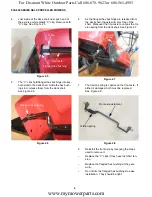
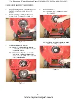
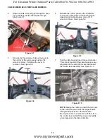
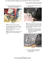
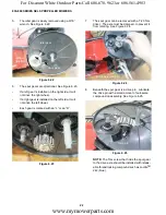
Draw the cable and spring up through the open-
ing in the deck that the cables pass through.
See Figure 5.7.
5.
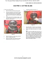
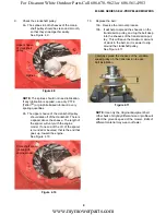
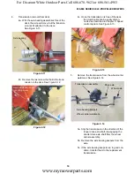
Remove the three screws holding the cover to
the bottom of the control panel using a 1/4”
wrench or driver. Pull-down the cover to
remove it. See Figure 5.8.
6.
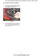
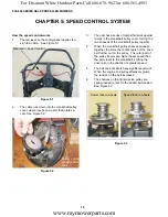
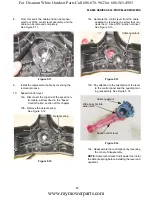
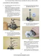
Beneath the control panel on the handlebar,
remove the cable clamp screw that holds the
speed control cable in place. Use a 5/16”
wrench or driver. See Figure 5.9.
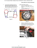
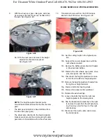
7.
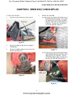
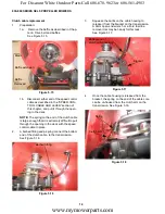
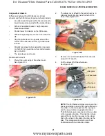
Pull the cable housing free of the control panel.
The stop at the end of the cable housing is usu-
ally placed in the notch that is second-nearest
the control lever assembly. See Figure 5.10.
NOTE:
Moving the cable to a notch that is closer
to the control lever will shift the range of avail-
able ground speeds in a slower direction.
Moving the cable to a notch that is further from
the control lever will shift the range of available
ground speeds in the faster direction.
Figure 5.7
Pull cable
Figure 5.8
Cover
Screws
Figure 5.9
Clamp screw
Figure 5.10
Second
notch
Speed control
cable housing
Cable core
www.mymowerparts.com
For Discount White Outdoor Parts Call 606-678-9623 or 606-561-4983


