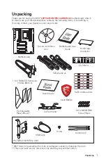
MSI X399 GAMING PRO CARBON AC Manual Download Page 1

1

Unpacking

Unpacking

Thank you for buying the MSI

®


X399 GAMING PRO CARBON AC


motherboard. Check 

to make sure your motherboard box contains the following items. If something is 

missing, contact your dealer as soon as possible.

SLI Bridge 

Connector

I/O Shield

Drivers & Utilities 

Disc

Motherboard User 

Guide

Quick Guide

OC Fan Stand

Motherboard

SATA Cable Labels

Case Badge

* MSI

®

 does not guarantee the risks or damages caused by changing the cover.

** These pictures are for reference only and may vary without notice.

SATA Cable x4

1 to 2 RGB LED Extension 

Y Cable 80cm x1

3D X-MOUNTING 

Screw Pillars

Exchangeable 

Plates Box x1*

Antenna x2 

Screw 

Wi-Fi/Bluetooth PCIe Card

USB Cable

Summary of Contents for X399 GAMING PRO CARBON AC

Page 1: ...onnector I O Shield Drivers Utilities Disc Motherboard User Guide Quick Guide OC Fan Stand Motherboard SATA Cable Labels Case Badge MSI does not guarantee the risks or damages caused by changing the c...

Page 2: ...computer before installation is completed This could cause permanent damage to the components as well as injury to the user y If you need help during any installation step please consult a certified c...

Page 3: ...raphics Card SATA Hard Disk Drive SATA DVD Drive A Package of Screws Phillips Screwdriver Torqkey Screwdriver Chassis Power Supply Unit Thermal Paste Quick Start Preparing Tools and Components AMD Ryz...

Page 4: ...4 Quick Start CPU Installing a Processor https youtu be yk4EpVUU03E 19 1 2 3 5 6 4 7 8 9 10 13 11 12 14 15 16 18 17...

Page 5: ...5 Quick Start Installing DDR4 memory http youtu be T03aDrJPyQs 1 2 2 3 D2 D1 C2 C1 CPU A1 A2 B1 B2 1 DIMM SocketTR4 CPU 2 DIMMs 4 DIMMs 8 DIMMs...

Page 6: ...9 JFP1 1 HDD LED 2 Power LED 3 HDD LED 4 Power LED 5 Reset Switch 6 Power Switch 7 Reset Switch 8 Power Switch 9 Reserved 10 No Pin R E S E T S W P O W E R S W P O W E R L E D P O W E R L E D H D D L...

Page 7: ...7 Quick Start Installing the Motherboard 1 2...

Page 8: ...8 Quick Start Installing SATA Drives http youtu be RZsMpqxythc 1 2 3 4 5...

Page 9: ...9 Quick Start 1 Installing a Graphics Card http youtu be mG0GZpr9w_A 2 3 4 5 6...

Page 10: ...10 Quick Start Connecting Peripheral Devices...

Page 11: ...11 Quick Start Connecting the Power Connectors http youtu be gkDYyR_83I4 ATX_PWR1 CPU_PWR1 CPU_PWR2 PCIE_PWR1...

Page 12: ...12 Quick Start Power On 1 4 2 3...

Page 13: ...Port LED Status Table 22 Realtek HD Audio Manager 23 Overview of Components 25 CPU Socket 27 OC1 GAME BOOST Knob 30 JSLOW1 Slow Mode Booting Jumper 31 DIMM Slots 32 PCI_E1 6 PCIe Expansion Slots 34 In...

Page 14: ...able 48 Boot Phases 48 Debug Code LED Table 48 ACPI States Codes 50 Changing Plates 51 Replacing heatsink plate 51 Replacing audio cover plate 51 Replacing I O cover plate 52 BIOS Setup 53 Entering BI...

Page 15: ...ts GAMING APP 80 X BOOST 85 MYSTICLIGHT 87 MSI SMART TOOL 89 RAMDISK 91 GAMING LAN MANAGER 92 DRAGON EYE 94 Nahimic 2 95 SteelSeries Engine 3 99 CPU Z 101 TriDef VR 102 TriDef SmartCam 105 Troubleshoo...

Page 16: ...1 slots Multi GPU y Supports 4 Way NVIDIA SLI Technology y Supports 4 Way AMD CrossFire Technology LAN 1x Intel I211 Gigabit LAN controller Wirsless LAN Bluetooth Intel Dual Band Wireless AC 8265 card...

Page 17: ...h speed USB ports 2 Type A ports on the back panel 4 ports available through the internal USB connectors y AMD CPU 8x USB 3 1 Gen1 SuperSpeed USB Type A ports on the back panel Audio y Realtek ALC1220...

Page 18: ...y 2x Front panel connectors y 1x Front panel audio connector y 2x RGB LED connector y 1x TPM module connector y 1x LED demo connector Provides additional power to PCIe x16 slots Internal Buttons y 1x...

Page 19: ...ivers y APP MANAGER y COMMAND CENTER y LIVE UPDATE 6 y SMART TOOL y DRAGON EYE y GAMING APP y X BOOST y MYSTIC LIGHT y RAMDISK y GAMING LAN MANAGER y Nahimic Audio y SteelSeriesEngine 3 y WTFast y CPU...

Page 20: ...light SYNC EZ DEBUG LED DDR4 Steel Armor M 2 Shield PCI E Steel Armor Multi GPU SLI Technology Multi GPU CrossFire Technology DDR4 Boost GAME Boost go to 11 OC Engine Clock gen USB with type A C Light...

Page 21: ...1 Gen2 Type C 3x M 2 PCIE Bus PCIE Bus Intel I211 Gigabit LAN DMI 3 0 PCI Express Bus X399 Processor NV6795 Super I O Realtek ALC1220 Intel 8265 WiFi 8x SATA 6Gb s 4x USB 3 1 Gen1 6x USB 2 0 8x USB 3...

Page 22: ...3 1 Gen2 Type A VR READY ports BIOS FLASHBACK port USB 3 1 Gen2 Type C BIOS FLASHBACK button Clear CMOS button y Clear CMOS button Power off your computer Press and hold the Clear CMOS button for abo...

Page 23: ...ou a complete guidance of anticipated sound effect for both output and input device y Main Volume controls the volume or balance the right left side of the speakers that you plugged in front or rear p...

Page 24: ...Rear I O Panel AUDIO INPUT Rear Front Side Center Subwoofer Audio jacks to headphone and microphone diagram Audio jacks to stereo speakers diagram Audio jacks to 7 1 channel speakers diagram AUDIO INP...

Page 25: ...JUSB2 JUSB1 JFP1 JSEL1 DEMOLED1 JCI1 JRGB1 JRAINBOW1 JFP2 JSLOW OC1 POWER1 RESET1 SYS_FAN2 SYS_FAN3 SYS_FAN4 SYS_FAN1 PCIE_PWR1 JBAT1 PCI_E1 M2_1 M2_2 M2_3 PCI_E2 PCI_E3 PCI_E4 PCI_E5 PCI_E6 JTPM1 JAU...

Page 26: ...CMOS Reset BIOS Jumper 44 JCI1 Chassis Intrusion Connector 43 JFP1 JFP2 Front Panel Connectors 38 JRGB1 JRAINBOW1 RGB LED connectors 45 JSLOW1 Slow Mode Booting Jumper 31 JTPM1 TPM Module Connector 43...

Page 27: ...s youtu be yk4EpVUU03E 1 Loosen load plate screws with the AMD Torx screwdriver in the sequence 3 2 1 The load plate will automatically lift up to the fully open position 3 2 1 2 Slide out the Externa...

Page 28: ...plate screws clockwise a little with the AMD Torx screwdriver in the sequence 1 2 3 1 2 3 until they are snug 5 Tighten load plate screws until you hear a click from the AMD Torx screwdriver Important...

Page 29: ...e or thermal tape between the CPU and the heatsink to enhance heat dissipation y Whenever the CPU is not installed always protect the CPU socket pins by covering the socket with the plastic cap y If y...

Page 30: ...75 GHz 3 85 GHz 3 55 GHz 4 15 GHz 2 3 8 GHz 3 9 GHz 3 6 GHz 4 2 GHz 4 3 85 GHz 3 95 GHz 3 65 GHz 4 25 GHz 6 3 9 GHz 4 GHz 3 7 GHz 4 3 GHz 8 3 95 GHz 4 05 GHz 3 75 GHz 4 35 GHz 10 4 GHz 4 1 GHz 3 8 GHz...

Page 31: ...Important y Users will try extreme low temperature overclocking at their own risks The overclocking results will vary according to the CPU version y Please don t switch to Enabled when power off or th...

Page 32: ...32 Overview of Components DIMM Slots DIMMD2 DIMMB2 DIMMB2 D2D1C2C1 A1A2B1B2 Memory module installation recommendation D2 D1 C2 C1 CPU Socket A1 A2 B1 B2 1 DIMM SocketTR4 CPU 2 DIMMs 4 DIMMs 8 DIMMs...

Page 33: ...rotect the CPU y Please note that the maximum capacity of addressable memory is 4GB or less for 32 bit Windows OS due to the memory address limitation Therefore we recommended that you to install 64 b...

Page 34: ...5 PCIe 2 0 x1 PCI_E6 PCIe 3 0 x8 Multiple graphics cards installation recommendation PCI_E1 PCI_E1 PCI_E1 PCI_E1 PCI_E3 PCI_E3 PCI_E4 PCI_E4 PCI_E4 PCI_E6 To prevent monitor blank during the system PO...

Page 35: ...raphics cards For power supply recommendations for SLI configurations please refer to the user guide of your graphics card to make sure you meet all the system requirements To install SLI graphics car...

Page 36: ...the USB connector on the card 3 Connect the other end of the USB cable to the USB 2 0 connector on the motherboard 4 Use the screw to secure the card 5 Screw the antennas tight to the RP SMA connecto...

Page 37: ...in the notch on the trailing edge of your M 2 module and tighten it into the base screw 4 Using M 2 shield We provide the M 2 shields on the M 2 slots to help dissipate heat away from the M 2 modules...

Page 38: ...identical plugs on either sides of the cable However it is recommended that the flat connector be connected to the motherboard for space saving purposes SATA3 SATA1 SATA5 SATA4 SATA2 SATA6 SATA7 SATA8...

Page 39: ...2V 4 Ground 8 12V Important y Make sure that all the power cables are securely connected to a proper ATX power supply to ensure stable operation of the motherboard y It is recommended that connect bot...

Page 40: ...3_RX_DN 9 USB2 0 19 Power 10 NC 20 No Pin Important Note that the Power and Ground pins must be connected correctly to avoid possible damage JUSB1 2 USB 2 0 Connectors These connectors allow you to co...

Page 41: ...the MSI SUPER CHARGER application to turn ON OFF the Charging mode Video Demonstration Watch the video to learn how to charge the smartphone with Super Charger http youtu be FCyvjr5NbOw Important Whe...

Page 42: ...nging voltage When you plug a 3 pin Non PWM fan to a fan connector in PWM mode the fan speed will always maintain at 100 which might create a lot of noise You can follow the instruction below to adjus...

Page 43: ...he chassis cover is opened again a warning message will be displayed on screen when the computer is turned on Resetting the chassis intrusion warning 1 Go to BIOS Settings Security Chassis Intrusion C...

Page 44: ...the jumpers to clear the CMOS memory Keep Data default Clear CMOS Reset BIOS Resetting BIOS to default values 1 Power off the computer and unplug the power cord 2 Use a jumper cap to short JBAT1 for a...

Page 45: ...has a plastic cap to prevent false connection of 5V LED strips Important y The JRGB1 connector supports 5050 RGB LED strips 12V G R B with the maximum power rating of 3A 12V y The JRAINBOW1 connector...

Page 46: ...s not detected or fail BOOT indicates the booting device is not detected or fail PCI_E1 LED PCI_E3 LED PCI_E4 LED PCI_E6 LED PCIe x16 slot LEDs These LED indicate the PCIe x16 slots status LED color P...

Page 47: ...control mode CPU_FAN1 LED PUMP_FAN1 LED LED light effect demonstration components These components are used by retailers to demonstrate onboard LED light effects JPWRLED1 LED power input DEMOLED1 Cha...

Page 48: ...s Codes 01 Power on Reset type detection soft hard 02 AP initialization before microcode loading 03 System Agent initialization before microcode loading 04 PCH initialization before microcode loading...

Page 49: ...DXE initialization CPU module specific 68 PCI host bridge initialization 69 System Agent DXE initialization is started 6A System Agent DXE SMM initialization is started 6B 6F System Agent DXE initial...

Page 50: ...ript Error EB S3 OS Wake Error EC EF Reserved for future AMI error codes Recovery Progress Codes F0 Recovery condition triggered by firmware Auto recovery F1 Recovery condition triggered by user Force...

Page 51: ...tip of the flat head screwdriver in a cloth Remove the plate Replace the plate by gently pressing it into the heatsink as shown above Use the flat end of the screwdriver into the corner of the plate a...

Page 52: ...gently pressing it into the audio cover as shown above Replace the plate by gently pressing it into the I O cover as shown above 3 4 3 1 Use your finger to pry the plate away from the I O cover as sh...

Page 53: ...erence only and may vary from the product you purchased Entering BIOS Setup Press Delete key when the Press DEL key to enter Setup Menu F11 to enter Boot Menu message appears on the screen during the...

Page 54: ...e BIOS Setup during POST 2 Insert the USB flash drive that contains the update file into the computer 3 Select the M FLASH tab and click on Yes to reboot the system and enter the flash mode 4 Select a...

Page 55: ...flash drive supports updating BIOS by BIOS FLASHBACK 1 Connect power supply to CPU_PWR1 CPU_PWR2 and ATX_PWR1 No other components are necessary but power supply 2 Plug the USB flash drive that contain...

Page 56: ...GAME BOOST function y XMP switch click on the inner circle to enable disable the X M P Extreme Memory Profile Switch the outer circle to select the X M P profile This switch will only be available if...

Page 57: ...ware Monitor menu that allows you to manually control the fan speed by percentage y Favorites press the Favorites tab or the F3 key to enter Favorites menu It allows you to create personal BIOS menu w...

Page 58: ...the descriptions of EZ Mode Overview section y BIOS menu selection the following options are available SETTINGS allows you to specify the parameters for chipset and boot devices OC allows you to adju...

Page 59: ...between time elements The time format is hour minute second f SATA PortX Shows the information of connected SATA devices Important If the connected SATA device is not displayed turn off computer and r...

Page 60: ...bles the onboard LAN controller fLAN Option ROM Disabled Enables or disables the legacy network Boot Option ROM for detailed settings This item will appear when Onboard LAN Controller is enabled Enabl...

Page 61: ...the operating system which does not support USB 3 0 Disabled Disables XHCI hand off support fLegacy USB Support Enabled Sets Legacy USB function support Auto The system will automatically detect if an...

Page 62: ...ake Up Event Setup Sets system wake up behaviors for different sleep modes Press Enter to enter the sub menu fWake Up Event By BIOS Selects the wake up event by BIOS or operating system BIOS Activates...

Page 63: ...hot key on PS 2 keyboard is detected Disabled Disables this function fHot Key Ctrl Space Selects a combination of keys as a hot key to wake the system This item appears when you set the Resume From S3...

Page 64: ...assword for system security User has limited rights to change the BIOS items with user password This item will be available when administrator password is set After setting the user password the state...

Page 65: ...rusion Disabled Enables or disables recording messages while the chassis is opened This function is ready for the chassis equips a chassis intrusion switch Enabled Once the chassis is opened the syste...

Page 66: ...is used to determine CPU clock speed This item can only be changed if the processor supports this function f Core Performance Boost Auto Enables or disables the Core Performance Boost CPB This item ap...

Page 67: ...hrottled when CPU temperature over the speci ed temperature If set to Auto BIOS will con gure this settings fVR 12VIN OCP Expander Auto Expands the limitation of VR Over Current Protection with 12V in...

Page 68: ...PU or memory has been replaced Enabled The system will issue a warning message during boot and then you have to load the default settings for new devices Disabled Disables this function and keeps the...

Page 69: ...lue of Spread Spectrum for EMI reduction y The greater the Spread Spectrum value is the greater the EMI is reduced and the system will become less stable For the most suitable Spread Spectrum value pl...

Page 70: ...rive that contains the update file into the computer 2 Click on M FLASH tab a demand message will be prompted Click on Yes to reboot and enter the flash mode 3 The system will enter the flash mode and...

Page 71: ...rrent overclocking pro le fLoad Overclocking Profile 1 2 3 4 5 6 Load the current overclocking pro le fClear Overclocking Profile 1 2 3 4 5 6 Clear the current overclocking profile f OC Pro le Load fr...

Page 72: ...Driver Disc into your optical drive 3 The installer will automatically appear and it will find and list all necessary drivers 4 Click Install button 5 The software installation will then be in progre...

Page 73: ...application had have been installed successfully and is available Double click on desired icon to access the application A refresh icon shows to inform you that the application has a update version Gr...

Page 74: ...ation tabs at the top You can click the tab to switch the control panel y Live Update When you launch LIVE UPDATE 6 you will see the Live update tab at first This tab allows you to select files to dow...

Page 75: ...he bottom 6 When Save Path prompt you can specify a download directory 7 When downloading you will see the screen below It may take several moments to complete the process 8 To install the application...

Page 76: ...trol Panel Previous Feature Next Feature Profile Buttons Option Buttons Page Indicator Resize Corner Profile Buttons y Default load the default values for the current feature y Apply apply your change...

Page 77: ...temperature The white dot will create strip chart in real time y System Fan Button to open the system fan control panel in new window y Fan Tune Button to automatically optimize the smart fan setting...

Page 78: ...eal time To filter record charts select the check box next to the items When click the Play button the chart pane will start to show the recording chart If you want to check the value of a specific sp...

Page 79: ...vate Wi Fi on your mobile device and connect to SoftAP with the SSID 6 Run MSI COMMAND CENTER APP on your mobile device 7 Find the IP address on the SoftAP Management Setting area and enter the IP add...

Page 80: ...nction Buttons allows you to use LED Effect OSD Eye Rest and Dragon Eye functions y Peripheral Device Function Buttons allows you to set the Gaming Hotkey Mouse Master and VR Ready functions y Remote...

Page 81: ...lows you to optimize the display on your monitor y EyeRest reduces blue light of your LED backlit screen in order to protect your eyes y Gaming automatically increase contrast ratio of your screen y M...

Page 82: ...nce of your system to ensure everything is VR Ready Applications VR ON OFF y VR ON OFF enables or disables VR settings y Applications appears when you turn on the VR support It allows you to close som...

Page 83: ...nd mouse macro recorder 2 Click on the Stop button to stop the recorder 3 Key in a file name and set up the parameter for the macro 4 Finally click on the Save button to save the recorded macro Window...

Page 84: ...he macro Left add a left click to the macro y Action List shows the actions of the current macro y Edit Buttons there 3 buttons for editing the macro Run activates the macro Delete removes the selecte...

Page 85: ...meet your current system environment or support faster storage access speed for your external storage or memory cards Easy In Easy page you can select one system performance mode to meet the current s...

Page 86: ...storage devices y Setting enables or disables Run X BOOST when windows starts y USB SPEED UP supports faster data transfer rates of the USB storage devices y STORAGE BOOST supports faster access spee...

Page 87: ...es will be controlled by the main screen y Live Preview gives you the full experience of your configuration s look feel while you are editing it y Light Effect Options allow you to customize lighting...

Page 88: ...ct of the motherboard y Motherboard Name shows the name of the motherboard y Live Preview gives you the full experience of your configuration s look feel while you are editing it y Light Effect Option...

Page 89: ...ate your installer Be sure to backup files on the USB drive this process will erase it To create the Windows installation USB drive Step1 Choose source folder y In the Source folder box type the name...

Page 90: ...ID in Windows system To create a software RAID 1 Use checkboxs to select the disks you want included in your RAID 2 Choose Speed Up or Backup for RAID type y Speed Up RAID0 y Backup RAID1 3 Click Star...

Page 91: ...etter Name Size and Format of the RAM disk y Option select browser temporary files to save load on the RAM disk You can also add software files to improve reading speed y Backup specify backup and res...

Page 92: ...ications by total traf c allows you to monitor network bandwidth usage y Network Test allows you to setup bandwidth control y Advanced Setting allows you to expand RWIN to accelerate download speed Yo...

Page 93: ...ollow the steps below 1 1 Click the Network Test block in GAMING LAN MANAGER 2 3 4 2 Click Test Network Speed button The test takes several minutes to test your network speed 3 Enter the testing resul...

Page 94: ...tions available WQVGA Small 400 240 HVGAW Medium 640 360 WVGA Large 768 480 y Position Settings allows you to determine how you want to position your DRAGON EYE windows on screen to avoid interfering...

Page 95: ...operties allows you to change the format sample rate bit rate and the channel gain of the current device if these options are available for the current device Clicks on this button and a device proper...

Page 96: ...urn on and off all Nahimic 2 s effects in one click y EQ Profile Page by clicking the arrow button you can also access a second page that contains the x10 bands EQ and EQ profiles EQ Profiles Custom E...

Page 97: ...access the audio launchpad and HD Audio Recorder 2 settings Audio Launchpad effects Control page Pad Properties y Audio Launchpad effects allows streamers to use prerecorded sounds during a livestrea...

Page 98: ...rovides a visual indication localizing the source of the strongest sound while in a game The Sound Tracker captions the 5 1 and 7 1 sound streams processed by your audio system and is displayed in all...

Page 99: ...regardless of type connection status or which applications they are assigned to y Library quickly set up your configurations to autolaunch with an application Application Configuration you can choose...

Page 100: ...Preview Revert Save Button y Widgets allow you to customize a certain aspect of your device y Widgets Toggle allows you to toggle Widgets y Configuration Windows Toggle allows you to toggle the Config...

Page 101: ...manufacturer model name chipset BIOS version and graphic interface y Memory Tab shows memory type memory size channels memory frequency y SPD Tab shows specifications relating to each memory module c...

Page 102: ...d to change your view of the surroundings A virtual screen will be visible in front of you This screen will initially be showing the Windows desktop While TriDef VR is running any Windows application...

Page 103: ...Games can be removed from the list by right clicking on the tile and selecting Remove The Edit option in the right click menu allows you to modify the game name and other properties Settings Tab The...

Page 104: ...dio setting is only available when TriDef VR is redirecting the audio from a different output so if the slider is disabled then use the normal Windows volume controls instead The Game FPS setting is p...

Page 105: ...d of your background Options When TriDef SmartCam is selected several advanced settings are also made available TriDef SmartCam s background replacement can operate in one of two modes In Normal mode...

Page 106: ...and then restart the computer y If 1 long 2 short beeps are heard remove and reinstall the graphics card and then restart the computer y Test with another known working graphics card The computer doe...

Page 107: ...pplicable European Harmonized Standards The point of contact for regulatory matters is MSI MSI NL Eindhoven 5706 5692 ER Son B B B VCCI B C Tick Compliance Battery Information European Union Batteries...

Page 108: ...u eraan herinneren dat De richtlijn van de Europese Unie EU met betrekking tot Vervuiling van Electrische en Electronische producten 2002 96 EC die op 13 Augustus 2005 in zal gaan kunnen niet meer bes...

Page 109: ...006 7 1 http www msi com html popup csr cemm_jp html http tw msi com html popup csr_tw cemm_jp html India RoHS This product complies with the India E waste Management and Handling Rule 2011 and prohib...

Page 110: ...ser guide please contact your place of purchase or local distributor Alternatively please try the following help resources for further guidance y Visit the MSI website for technical guide BIOS updates...

Reviews: