18
Graphics
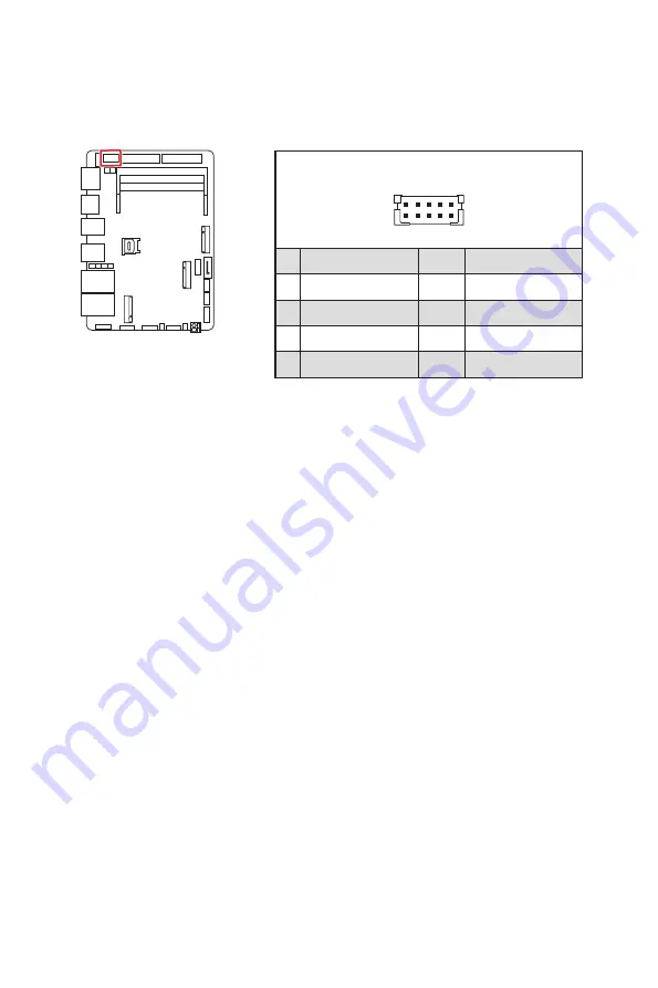
JINV1: LVDS Inverter Box Header
The connector is provided for LCD backlight options.
JINV1
1
2
10
9
GND
3
VCC5
4
5
+12V
6
7
INV_ON#1
8
INV_ON#2
L_BKLT_CTRL#1
L_BKLT_CTRL#2
Page 1: ...MS 98M3 Industrial Computer Board User Guide...
Page 2: ...tion 6 Battery 6 CE Conformity 7 FCC B Radio Frequency Interference Statement 7 Specifications 8 Rear I O Panel 11 DisplayPort 11 HDMI Connector 11 USB 3 2 Gen 2 Port 11 RJ 45 LAN Port 11 Overview of...
Page 3: ...COM Port Box Header RS232 422 485 21 JAUD1 Audio Amplifier SMbus Connector 22 JGPIO1 GPIO DIO Connector 23 Jumper 24 Expansion Slot 25 USIM1 Nano SIM Holder 25 M2_E1 M 2 Slot E Key 2230 26 M2_B1 M 2 S...
Page 4: ...further guidance Green Product Features Reduced energy consumption during use and stand by Limited use of substances harmful to the environment and health Easily dismantled and recycled Reduced use o...
Page 5: ...e computer before installation is completed This could cause permanent damage to the components as well as injury to the user If you need help during any installation step please consult a certified c...
Page 6: ...acturer Avoid disposal of a battery into fire or a hot oven or mechanically crushing or cutting of a battery which can result in an explosion Avoid leaving a battery in an extremely high temperature o...
Page 7: ...ul interference to radio or television reception which can be determined by turning the equipment off and on the user is encouraged to try to correct the interference by one or more of the measures li...
Page 8: ...Mobile Tiger Lake UP3 Core i3 1115GRE DC 28W Chipset Within processor iAMT Support AMT 15 0 supported Only for Intel i7 i5 CPU series not support G3 to S5 Memory 2 x DDR4 SO DIMM slots Dual Channel f...
Page 9: ...ector Rear Panel I O 1 x DisplayPort 1 x HDMI connector 4 x USB 3 2 Gen 2 Type A ports 10Gbps 2 x RJ 45 2 5 GbE LAN ports Expansion Slots 1 x M 2 B Key 2242 3042 slot With PCIe x1 SATA 3 0 USB 2 0 sig...
Page 10: ...ode select jumper 2 x COM1 4 select jumpers 1 x ME jumper Form Factor 3 5 inch size 146mm L x 102mm W ACPI G3 to S5 mode does not support Environment Operating Temperature Embedded Non WT SKUs 10 60 C...
Page 11: ...dard enhanced or high definition video plus multi channel digital audio on a single cable USB 3 2 Gen 2 Port USB 3 2 Gen 2 the SuperSpeed USB 10Gbps delivers high speed data transfer for various devic...
Page 12: ...view of Components JINV1 JAUD1 JGPIO1 JCOM1_2 JCOM3_4 JCOMP1 JCOMP2 JPWR1 JFP1 JUSB1 JUSB2 M2_E1 SATA1 M2_M1 M2_B1 JPW1 DIMM2 DIMM1 JME_DIS1 JCOMS1 JATX1 JLVDS1_EDP1 JLVDS2_EDP2 Rear Panel I O USIM1 J...
Page 13: ...Key 2280 16 Graphics JLVDS1_EDP1 JLVDS2_EDP2 LVDS eDP Box Header 17 JINV1 LVDS Inverter Box Header 18 Connector SYSFAN1 System Fan Header 19 JUSB1 2 USB 2 0 Box Header 20 JFP1 Front Panel Box Header 2...
Page 14: ...y downwards until the slot levers click and lock the DIMM in place 3 To uninstall the DIMM flip the slot levers outwards and the DIMM will be released instantly Important You can barely see the golden...
Page 15: ...of the power supply is inserted in the proper orientation and the pins are aligned Then push down the power supply firmly into the connector JPW1 SATA Power Connector This connector is used to provide...
Page 16: ...cable at a 90 degree angle Data loss may result during transmission otherwise SATA cables have identical plugs on either sides of the cable However it is recommended that the flat connector be connect...
Page 17: ..._7513_R 6 DDC0_DATA_7513_R 7 LCD_VDD 8 LCD_VDD 9 LCD_VDD 10 VCC3 11 BKLT_EN 12 LVDS_DETECT 13 LVDSA_DATA1 14 EHPDET LVDSA_DATA0 15 LVDSA_DATA1 16 LVDSA_DATA0 17 GND 18 GND 19 LVDSA_DATA3 20 LVDSA_DATA...
Page 18: ...8 Graphics JINV1 LVDS Inverter Box Header The connector is provided for LCD backlight options JINV1 1 2 10 9 1 GND 2 GND 3 VCC5 4 VCC5 5 12V 6 12V 7 INV_ON 1 8 INV_ON 2 9 L_BKLT_CTRL 1 10 L_BKLT_CTRL...
Page 19: ...nected to the 12V the black wire is Ground and should be connected to GND If the motherboard has a System Hardware Monitor chipset onboard you must use a specially designed fan with speed sensor to ta...
Page 20: ...Front Panel Box Header This front panel connector is provided for electrical connection to the front panel switches LEDs and is compliant with Intel Front Panel I O Connectivity Design Guide 1 HDD LED...
Page 21: ...FIFOs You can attach a serial device to it RS232 RS422 RS485 1 2 DCD 1 2 TXD 1 2 D 3 4 RXD 3 4 TXD 3 4 D 5 6 TXD 5 6 RXD 5 6 NC 7 8 DTR 7 8 RXD 7 8 NC 9 10 GND 9 10 GND 9 10 GND 11 12 DSR 11 12 NC 11...
Page 22: ...unction to enhance audio performance and SMBus known as I2C for connecting System Management Bus SMBus interface 1 LINE_IN_RA 2 MIC1_RA 3 LINE_IN_LA 4 MIC1_LA 5 LOUT_RA 6 MIC1_JD 7 LOUT_LA 8 LINE1_JD...
Page 23: ...nnector is provided for the General Purpose Input Output GPIO peripheral module JGPIO1 1 20 19 2 1 GND 2 GND 3 GPO0 4 GPI0 5 GPO1 6 GPI1 7 GPO2 8 GPI2 9 GPO3 10 GPI3 11 GPO4 12 GPI4 13 GPO5 14 GPI5 15...
Page 24: ...will damage the motherboard JCOMP1 JCOMP2 JME_DIS1 JCOMS1 JATX1 JVDD2 JVDD1 1 3 2 Jumper Name Default Setting Description JVDD1 JVDD2 1 1 2 3V 2 3 5V JME_DIS1 1 1 2 Normal 2 3 ME Disable JCMOS1 1 1 2...
Page 25: ...25 Expansion Slot Expansion Slot M2_B1 M2_E1 USIM1 USIM1 Nano SIM Holder This holder is provided for 3G 4G LTE 5G Nano SIM cards...
Page 26: ...M2_E1 slot supports PCIe x 1 USB 2 0 signal M2_B1 M 2 Slot B Key 2242 3042 Please install the WWAN Card solid state drive SSD into the M 2 slot as shown below 2 3 4 1 Feature Supports PCIe x 1 SATA 3...
Page 27: ...apter should be held for reference only Entering Setup Power on the computer and the system will start POST Power On Self Test process When the message below appears on the screen press DEL or F2 key...
Page 28: ...of the highlighted setup function is displayed at the bottom of the screen Sub Menu If you find a right pointer symbol appears to the left of certain fields that means a sub menu can be launched from...
Page 29: ...y 35 Active Processor Cores 35 Hyper Threading 35 Intel R SpeedStep TM 35 Turbo Mode 36 C States 36 Memory Configuration 37 In Band ECC Support 37 Super IO Configuration 38 Serial Port 1 2 3 4 38 FIFO...
Page 30: ...n 45 Anti Rollback SVN Configuration 46 AMT Configuration 47 USB Provisioning of AMT 47 CIRA Configuration 47 ASF Configuration 48 Secure Erase Configuration 48 OEM Flag Setting 49 MEBx Resolution Set...
Page 31: ...4 Type Select 54 Panel 1 2 Backlight Control 54 Power 55 Restore AC Power Loss 55 Deep Sleep Mode 55 OnChip USB 55 PCIE PME 55 RTC 55 Save Exit 56 Save Changes and Reset 56 Discard Changes and Exit 56...
Page 32: ...to specify the priority of boot devices Security Use this menu to set supervisor and user passwords Chipset This menu controls the advanced features of the onboard chipsets Power Use this menu to spec...
Page 33: ...nute Second SATA Mode Selection This setting specifies the SATA controller mode AHCI AHCI Advanced Host Controller Interface is a technical standard for an interface that allows the software to commun...
Page 34: ...delay to the booting sequence This delay ensures that the logo is displayed for a sufficient amount of time Therefore it is recommended that you disable this BIOS feature for a faster boot up time Bo...
Page 35: ...treats the two cores inside the processor as two logical processors that can execute instructions simultaneously In this way the system performance is highly improved If you disable the function the...
Page 36: ...Enables this function to boost CPU performance automatically over specification when system request the highest performance state Disabled Disables this function C States This setting controls the C S...
Page 37: ...portion 1 32 of memory space will be reserved to store ECC data Disabled Disables this function In Band ECC Error Injection Enables or disables In Band ECC Error Injection This feature only display wh...
Page 38: ...Mode Select Select an operation mode for Serial Port 1 2 3 4 FIFO Mode This setting controls the FIFO data transfer mode Shared IRQ Mode This setting provides the system with the ability to share inte...
Page 39: ...urrent status of all monitored hardware devices components such as voltages temperatures and all fans speeds Thermal Shutdown This setting enables disables the Thermal Shutdown function It will automa...
Page 40: ...avoiding the overheating to damage your system Network Stack Configuration This menu provides Network Stack settings for users to enable network boot PXE from BIOS Network Stack This menu provides Ne...
Page 41: ...41 BIOS Item Contents GPIO Group Configuration GPO0 GPO7 These settings control the operation mode of the specified GPIO...
Page 42: ...42 BIOS Item Contents Boot Boot Option Priorities This setting allows users to set the sequence of boot devices where BIOS attempts to load the disk operating system...
Page 43: ...istrator Password controls access to the BIOS Setup utility User Password User Password controls access to the system at boot and to the BIOS Setup utility Intel BIOS Guard Support Intel BIOS Guard Su...
Page 44: ...Firmware Status 2 ME State This setting specifies the Intel Management Engine state ME Unconfig on RTC Clear This setting enables disables ME firmware unconfigure on RTC clear Comms Hub Support This s...
Page 45: ...osoft Windows TPM Device Selection Select TPM Trusted Platform Module devices from PTT or dTPM Discrete TPM PTT Enables PTT in SkuMgr dTPM1 2 Disables PTT in SkuMgr Warning PTT Discrete TPM will be di...
Page 46: ...etting DOI3 bit for all HECI devices MCTP Broadcast Cycle This setting enables disables Management Component Transport Protocol MCTP Broadcast Cycle Anti Rollback SVN Configuration Automatic HW Enforc...
Page 47: ...re based technology for remotely managing and securing PCs out of band USB Provisioning of AMT Enables or disable USB Provisioning of AMT CIRA Configuration Activate Remote Assistance Process Setting...
Page 48: ...isplays OS Timer BIOS Timer This item displays BIOS Timer ASF Sensor Table This setting enables disables Alert Standard Format ASF Sensor Table Secure Erase Configuration Secure Erase Mode This settin...
Page 49: ...configure ME Confirmation Prompt This setting enables disables the Hide Unconfigure ME Confirmation Prompt MEBx OEM Debug Menu Enable This setting enables disables the MEBx OEM Debug Menu Unconfigure...
Page 50: ...will appear Set this item to TPM Clear to clear all data secured by TPM or None to discard the selection It is advised that users should routinely back up their TPM secured data Platform Hierarchy St...
Page 51: ...r and keyboard attached This setting enables disables the operation of console redirection When set to Enabled BIOS redirects and sends all contents that should be displayed on the screen to the seria...
Page 52: ...e bits per second data bits parity stop bits of Console Redirection Flow Control Flow control is the process of managing the rate of data transmission between two nodes It s the process of adjusting t...
Page 53: ...nsole Redirection Setting page for more help with Terminal Type Emulation Flow Control EMS Windows Emergency Management Service Flow control is the process of managing the rate of data transmission be...
Page 54: ...hen Panel 1 Function is enabled LCD Panel Type This setting specifies the LCD Panel s resolution and distribution formats The item will display when Panel 1 Type is set to LVDs Panel 1 2 Backlight Con...
Page 55: ...except that the PSU still supplies power at a minimum to the power button to allow return to S0 A full reboot is required No previous content is retained Other components may remain powered so the com...
Page 56: ...timized Defaults Use this menu to load the default values set by the motherboard manufacturer specifically for optimal performance of the motherboard Save as User Defaults Save changes as the user s d...