background image


Quick Start 

35 

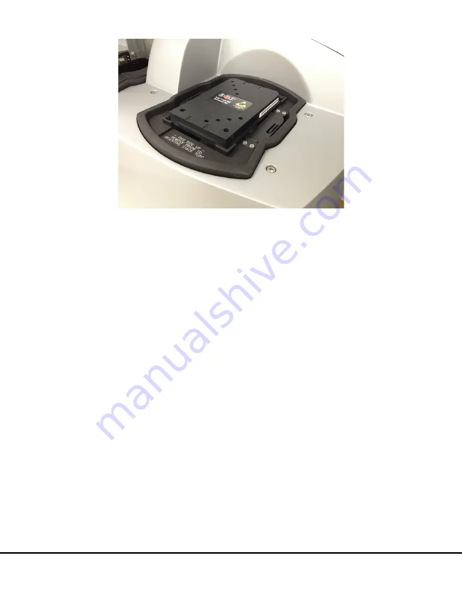
Figure 5:7 SECTOR Imager demonstration plate in the single plate adaptor 


NOTE: If the SECTOR Imager is unable to read the barcode on the demonstration plate (or if no barcode label is present), the 
plate will be skipped  and ejected from the instrument. Please  contact MSD 

Scientific and Technical Support

  for 

assistance. 

5.3


Run 

When the camera reaches proper operating temperature, the Instrument Log (click Show Log in the Status window) will indicate that 
the temperature is locked. At that point, the instrument is ready. 

Click Run in the SECTOR Imager window. The Run Options dialog window will open (

Figure 5:8

).


1.


Verify  Setup Selections.  If changes are necessary, click Cancel,  make changes in the area  (

5.2  Setup

)  of the SECTOR 

Imager window, and re-verify Setup Selections. 

2.


Run name is optional, but one can be entered in the second section. 

3.


Verify the Export  information and make changes if necessary.  (Refer to the  DISCOVERY  WORKBENCH  User Guide  for 
additional details.) The export selections control the format and the location of the exported text data file that will be created 
when the demonstration plate is read. 

4.


Click 

OK

. The plate read starts. View the status in the lower left region (Status bar) of the DISCOVERY WORKBENCH 

software to monitor progress. When the plate read is complete, the demonstration plate is returned to the stacker and 

Run

 is 

enabled again. 

5.3.1


Operations 

The Pause, Stop, Eject, and Retract buttons operate the motion control system that moves plates through the instrument. 


Pause. Pauses the plate read. Selecting Pause again resumes the read. 


Stop. Stops the current run and ejects any plate inside the instrument. 


Eject. Transfers a plate from inside the instrument (but not being read) to the stacker output port where it may be retrieved. 
This function is disabled during a plate run. 


Retract. Moves a plate from the input port into the instrument. No further action is taken without input from the operator. 
This function is disabled during a plate run. 

Summary of Contents for SECTOR Image 2400

Page 1: ...SECTOR Imager Models2400 6000 INSTRUMENT MANUAL www mesoscale com ...

Page 2: ...information contained in this Manual is subject to change without notice Unauthorized Use of Manual Material No part of this Manual may be duplicated reproduced stored in a retrieval system translated transcribed or transmitted in any form or by any means without the express prior written permission of MSD This Manual shall be returned to MSD within two 2 business days following any request by MSD...

Page 3: ...y 16 3 4 System Components 17 3 5 The SECTOR Imager 17 3 5 1 CCD Camera and Telecentric Lens 18 3 5 2 Motion Control System 19 3 5 3 Plate Barcode Readers 19 3 5 4 MULTI ARRAY Plate Input Output Stacker 19 3 5 5 Stack Tubes 19 3 5 6 Single Plate Adaptor 20 3 5 7 Stacker Cover Plate 21 3 5 8 Status LEDs 21 3 5 9 Power Switch and Input Output I O Panel 22 3 5 10 Halt Button 23 3 6 Microsoft Windows ...

Page 4: ...9 2 Problems Running SECTOR Imagers 55 9 3 How to Contact Us 55 ListofFigures Figure 2 1 SECTOR Imager electrical hazards SECTOR Imager 6000 shown 11 Figure 3 1 SECTOR Imager system SECTOR Imager 6000 shown 17 Figure 3 2 SECTOR 6000 Imager components 18 Figure 3 3 Input right stacker interface plate 20 Figure 3 4 Fully loaded standard and high capacity stack tubes 20 Figure 3 5 SECTOR Imager plate...

Page 5: ...adapter in the input port 34 Figure 5 7 SECTOR Imager demonstration plate in the single plate adaptor 35 Figure 5 8 SECTOR Imager window Run Options dialog box 36 Figure 5 9 Demonstration plate results Color Map layer 37 Figure 6 1 Loading MULTI ARRAY plates into stack tube 40 ListofTables Table 3 1 Stack tube plate capacities 19 Table 8 1 Troubleshooting guide 46 Table 8 2 Scientific performance ...

Page 6: ...6 1 Introduction ...

Page 7: ...ebsite at www mesoscale com 1 1 Intended Audience This manual is for all users of the SECTOR Imagers Users should understand general computer and Microsoft Windows terminology and be familiar with standard laboratory practices The intended users of the SECTOR Imagers are those conducting research in the life sciences The SECTOR Imager 2400 2400A and SECTOR Imager 6000 share many features Throughou...

Page 8: ...est results CAUTION Carefully read and understand all information in this document Failure to read understand and follow the instructions in this publication may result in damage to the product injury to operating personnel or poor instrument performance 1 3 Formatting Information This guide uses the following formatting conventions Internal hyperlinks are formatted bold gray Click to jump instant...

Page 9: ...9 2 ImportantInformation ...

Page 10: ...ating system power features that disable USB communication such as Hibernate will cause the system to stop responding and requires a power off on cycle of the instrument and PC to restore function CAUTION Additional USB devices may not be connected to the SECTOR Imager computer system CAUTION Changes to the computer clock can cause a system error if the changes are made during a plate read A syste...

Page 11: ... AC voltages DO NOT ATTEMPT TO SERVICE OR REPAIR THE SECTOR IMAGER Please contact MSD Instrument Service for all service and repair including electrical problems When the power switch is in the off position all internal electrical circuits are disconnected from both the live and neutral lines of the electrical power source On Off WARNING For best performance remove any sample or reagent spillage f...

Page 12: ...ese reagents Product labels package inserts and product information sheets with specific usage recommendations are provided for all plates and reagents used with the SECTOR Imager Contact MSD Scientific and Technical Support to obtain material safety data sheets MSDS for MSD plates and reagents Samples user reagents or controls used in assays may be infectious or biohazardous By working with these...

Page 13: ...r operate the instrument unless both stacker ports contain a single plate adaptor Figure 3 5 a stack tube Figure 3 4 or the stacker cover plate Figure 3 5 2 2 5 ESD Sensitivity The SECTOR Imager has been tested for electrostatic discharge ESD sensitivity and complies with the applicable international standards Standard installation precautions should be taken when stationing the instrument for reg...

Page 14: ... are sure that the instrument will not be in use Occasionally Windows Update does not restart the database server after it runs This will cause the instrument software to run incorrectly Restarting the computer will restart the database service and restore the instrument to full operation The SECTOR Imager system has not been tested for compatibility with all programs Installation of additional ap...

Page 15: ...15 3 SystemDescription ...

Page 16: ...oftware all models provide the capability to interact with a third party external robotic controller 3 3 Plate Compatibility The SECTOR Imager 2400A is compatible with 96 well MULTI ARRAY plates 96 well 4 7 and 10 spot MULTI SPOT plates The SECTOR Imager 2400 is compatible with 96 and 384 well MULTI ARRAY plates 96 well 4 7 and 10 spot MULTI SPOT plates The SECTOR Imager 6000 is compatible with 96...

Page 17: ...2400A models 1250 1251 power RS 232 USB and camera serial cable Cables SECTOR Imager 6000 model 1201 power and USB Uninterruptible power supply UPS SECTOR Imager 2400 and 6000 Instrument Manual DISCOVERY WORKBENCH User Guide Figure 3 1 SECTOR Imager system SECTOR Imager 6000 shown 3 5 The SECTOR Imager The main components of the SECTOR Imager include Figure 3 2 CCD camera and telecentric lens Moti...

Page 18: ...ferent custom lens optimized to read MULTI ARRAY plates in 24 sectors not shown 3 5 1 CCD Camera and Telecentric Lens Each SECTOR Imager uses a sensitive high resolution CCD camera and lens system to detect light emitted from MULTI ARRAY plates The SECTOR Imager 2400 2400A reads plates using 24 sectors or segments The SECTOR Imager 6000 reads plates using 6 sectors or segments yielding higher thro...

Page 19: ...he stacker will automatically pull plates from the input right side and eject them into the output left side The stacker may be used with two single plate adaptors or two stack tubes or one of each Stacker cover plates or single plate adaptors containing an empty plate should be used over the stacker interface plates whenever the machine is not in use When running single plates the input right sta...

Page 20: ...ager reads single plates placed manually into the single plate adaptor When inserting the single plate adaptor into the stacker ensure that the single plate adaptor is fully seated on the stacker interface plate Figure 3 5 right side of image shows a single plate properly loaded in the single plate adaptor The single plate adaptor may also be used with laboratory robotics ...

Page 21: ...urn plates to the input side A stacker cover plate is preinstalled on the output port Figure 3 5 SECTOR Imager plate in single plate adaptor A stacker cover plate should always be in place when no stack tube or single plate adaptor is present 3 5 8 Status LEDs The status LEDs built into the camera tower indicate the current operational mode of the SECTOR Imager Figure 3 6 Steady blue Instrument is...

Page 22: ...instrument can be powered on and off via the power switch Typically the instrument should be left powered on to maintain camera temperature NOTE Only use the communications cables supplied with the SECTOR Imager Use of cables other than those supplied may degrade instrument performance A halt connector is present in order to add an external switch that will de energize the motion control system Th...

Page 23: ...till pose a shock hazard NOTE For SECTOR Imager 6000 model 1201 this switch is on off If it is pressed for any reason all motion will halt It must be pressed again before the motion system and software will function For SECTOR Imager 6000 model 1200 and SECTOR Imager 2400 2400A the halt switch is a momentary switch so this not a concern The halt switch should never be obstructed or restricted from...

Page 24: ...Y WORKBENCH application software 3 7 MSD DISCOVERY WORKBENCH Software The workstation includes a personal computer display keyboard and mouse The instrument computer and its software are an integral part of the system and should only be modified by a MSD service engineer I O connections on the associated computer workstation are shown in Figure 3 9 Figure 3 9 Cable attachment locations for SECTOR ...

Page 25: ...be loaded either manually or by robotic plate handling equipment In this mode the stacker cover plate should be placed over the interface for safety The two position single plate handling mode uses a single plate adaptor on the input side for loading and a second single plate adaptor on the output side for unloading The single plate loading and stack unloading mode uses the single plate adaptor on...

Page 26: ...Figure 3 12 as read by the SECTOR Imager 6000 The demonstration plate for the SECTOR Imager 2400 2400A not shown uses a different electrode configuration designed to match the SECTOR Imager 2400 2400A Figure 3 12 SECTOR Imager 6000 Demonstration Test Plate For the SECTOR Imager 6000 sectors 3 and 4 of the demonstration plate have LEDs that test the CCD camera in the SECTOR Imager The remaining fou...

Page 27: ...wer Supply The SECTOR Imager should be operated with an uninterruptible power supply UPS to ensure the integrity of data in the event of power line transients The UPS required will depend on the standard operating voltage at your laboratory s location Please ensure that the proper UPS is employed for the power conditions in your country and local area NOTE Although the SECTOR Imager has been teste...

Page 28: ...28 4 Installation ...

Page 29: ... system or installing any software that changes parameters of the computer environment could interfere with proper operation of the instrument software CAUTION Running virus checking software screen savers maintenance software network security software and possibly other software on the SECTOR Imager computer could cause conflicts with the operation of the instrument software CAUTION Use of other ...

Page 30: ...30 5 QuickStart ...

Page 31: ...ating temperature either 25 1 C or 35 1 C for the SECTOR Imager 2400 2400A and SECTOR Imager 6000 respectively must be reached before the DISCOVERY WORKBENCH software will allow the processing of any plates The Status window displays the temperature of the CCD camera while it is cooling Figure 5 1 Once the CCD camera has reached its operating temperature the temperature indicator will disappear in...

Page 32: ...start automatically double click the MSD DISCOVERY WORKBENCH icon on the Windows desktop Figure 5 2 Figure 5 2 MSD DISCOVERY WORKBENCH desktop icon 4 Click the SECTOR Imager icon Figure 5 3 on the toolbar to connect to the imager and initiate the CCD camera cooling process Figure 5 3 SECTOR Imager icon The SECTOR Imager splash screen Figure 5 4 will display while the instrument is initializing If ...

Page 33: ...onstration plate will be run as a single plate it is most convenient to return it to the input stack after processing NOTE It is very important to select Return Plates to Input Stack checkbox when the stacker cover plate is on the output stack so that the SECTOR Imager will not attempt to place the plate into the covered interface at the end of the read The SECTOR Imager 2400A has a cover plate pe...

Page 34: ...ker interface plate Figure 5 6 Figure 5 6 Stacker cover over the output port with empty single plate adapter in the input port 6 Load the SECTOR Imager demonstration plate into the single plate adaptor Figure 5 7 Sensors in the instrument will automatically identify the plate orientation and adjust the data acquisition and analysis accordingly ...

Page 35: ...changes if necessary Refer to the DISCOVERY WORKBENCH User Guide for additional details The export selections control the format and the location of the exported text data file that will be created when the demonstration plate is read 4 Click OK The plate read starts View the status in the lower left region Status bar of the DISCOVERY WORKBENCH software to monitor progress When the plate read is c...

Page 36: ...Quick Start 36 Figure 5 8 SECTOR Imager window Run Options dialog box ...

Page 37: ... 2000 and dark wells should display numbers below 200 Figure 5 9 shows a Color Map view of the data from the demonstration plate Figure 5 9 Demonstration plate results Color Map layer When using the SECTOR Imager 6000 demonstration plate sectors 3 and 4 Figure 3 10 should display four bright wells each as shown in Figure 5 9 Sectors 1 2 5 and 6 should have uniform low signal levels corresponding t...

Page 38: ...38 6 UsingtheSECTORImager ...

Page 39: ...plate The SECTOR Imager except the SECTOR Imager 2400A will automatically pull plates from the right side and eject plates into the left side If the stacker cover plate is present on the output stack remember to select the Return Plates to Input Stack checkbox so that the SECTOR Imager will not attempt to place the plate into the covered stack at the end of the read The SECTOR Imager 2400A is conf...

Page 40: ... plate adaptor if it is present on the stacker 6 Place the full stack tube on the input right stacker interface plate 7 Place an empty stack tube of the same size on the output left stacker interface plate Figure 6 1 Loading MULTI ARRAY plates into stack tube If the stack of plates to be run is too tall for the above procedure you can insert the additional plates through the top of the stack tube ...

Page 41: ...the output stack The plates should be removed manually by sliding them up and out the top of the stack tube The last few plates can be accessed by pushing the last plate up from the bottom of the stack tube 6 3 Robotics Integration All SECTOR Imagers can be integrated with a robotics system for loading and unloading plates using the Remote Instrument Mode which allows the instrument to be used as ...

Page 42: ...42 7 Maintenance ...

Page 43: ... usually once every 6 months Contact MSD Customer Service to ask about our service contracts 7 2 Instrument Cleaning Reasonable care should be taken to prevent unnecessary fluid spills onto and into the SECTOR Imager Any spills onto the instrument should be promptly cleaned using either water 70 ethanol 1 bleach in water or a mild detergent Choose a cleaning solvent that is appropriate for the nat...

Page 44: ...pletely If plate loading problems persist contact Scientific and Technical Support 7 3 Instrument Decontamination Contact MSD Scientific and Technical Support for a detailed protocol for instrument decontamination NOTE The SECTOR Imager must be decontaminated prior to shipping the instrument back to MSD Contact MSD Scientific and Technical Support prior to shipping for instructions and requirement...

Page 45: ...45 8 Appendix ...

Page 46: ...e whether your IT department has made any changes to the instrument computer recently Incompatible anti virus software has been installed on the instrument computer Disable the antivirus program temporarily to see if that is the issue There are several methods 1 Exclude the file C Program Files MSD Discovery Workbench lib prefs properties from scanning 2 Disable real time scanning 3 Uninstall the ...

Page 47: ... layout Ensure that each text field does not contain more than 9 numbers For example shorten Sx379 2012 04 24 1638400 to Sx379 16384 Avoid using invalid characters etc in text fields Error 5216 Unable to locate file An inventory file has become corrupted DISCOVERY WORKBENCH v3 only Perform the following steps 1 Completely close DISCOVERY WORKBENCH 2 Go to C Program Files MSD DISCOVERY WORKBENCH Da...

Page 48: ...he SECTOR Imager and the instrument computer for 30 seconds 2 Start the computer and then start the SECTOR Imager 3 Wait for five minutes and then launch DISCOVERY WORKBENCH If the problem persists 1 Click Start and select Settings then Control Panel 2 Go to Administrative Tools and click Event Viewer 3 Right click Application and select Properties A dialog window will appear 4 Increase the log si...

Page 49: ...er 5 Wait five minutes before starting the MSD DISCOVERY WORKBENCH software If the problem is not resolved contact Scientific and Technical Support Error 11668 Audit Event Issue The software was unable to add an event to the Windows event log DISCOVERY WORKBENCH v3 only Perform the following steps 1 Right click My Computer select Manage and then click Event Viewer 2 Right click Application 3 Selec...

Page 50: ... R92TE 2 12 000 18 000 counts 25 100 counts 12 000 18 000 counts 25 100 counts Dynamic Range 10 6 10 6 Electronic Noise Standard Deviation Dark Noise depends on plate type 0 16 counts 0 16 counts 8 2 3 Environmental Specifications Suggested Operational Temperature Range 20 26 C 68 78 F Suggested Operational Humidity Range 10 80 non condensing Storage Temperature Range 5 40 C 41 104 F Storage Humid...

Page 51: ...per label font size and location of custom bar code on plate Recognition of additional codes is possible but has not been tested 8 2 8 Plate Specifications MSD MULTI ARRAY and MULTI SPOT plates are designed to comply with the mechanical dimensions of the proposed standards of the Society of Biomolecular Screening Contact MSD Scientific and Technical Support for further details The MULTI ARRAY and ...

Page 52: ...unications Operation of this equipment in a residential area is likely to cause harmful interference in which case users will be required to correct the interference at their own expense Regarding Industry Canada Interference Causing Equipment Standard This Class A digital apparatus complies with Canadian ICES 003 Cet appareil numérique de la Classe A est conforme à la norme NMB 003 du Canada Cont...

Page 53: ... Warning Electrostatic Sensitive Device V Volts A Amps Alternating Current On Off Halt plate motion system European Compliance Mark Indicates that the device complies with applicable European Directives USB I O Port Symbol and Reference Designation or Camera Controller Serial I O Port Symbol and Reference Designation Bar Code Reader RS 232 I O Port Symbol and Reference Designation or External Stop...

Page 54: ...54 9 TechnicalSupport ...

Page 55: ... the error occurred How can the error be reproduced If requested by MSD Scientific Support a copy of the SysInfoOutput txt file located in C sysinfo To generate the report file first run the SysInfo exe diagnostic tool located in WinXP Win7 32 bit C Program Files MSD DISCOVERY WORKBENCH bin Win7 64 bit C Program Files x86 MSD DISCOVERY WORKBENCH bin Email this information to scientificsupport meso...

Page 56: ...Technical Support 9 2 ...

Reviews: