


MSA AUER
MSA
Installation
SUPREMATouch
201
US
10.10 System Ports (MST Module)
The system expansions and system connections described in the following can be realised by us-
ing the MST module, plugged into the rear of the rack.
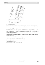
Fig. 141 MST Module Connections as from Module version 8
Fig. 142 SUB-D pin assignment
For simplification of the CAN bus connection at systems with several racks, the MST module has
been revised. For every CAN bus an additional connection was added so that the T pieces are
saved when connecting racks (Chapter 10.5).
CAN Bus Ports (CAN-A/CAN-B)
The two system buses in the system, i.e., CAN-A and CAN-B, are provided to allow expansion of
the system (systems with several racks). The measurement value input (MDA + MAI module) or
the switching outputs (MGO module) can be set up separately from the main rack to reduce the
cabling. In systems without redundancy, the individual racks are connected to each other by
ready-made CAN bus cables via the CAN-A bus port (Chapter 10.4).
Summary of Contents for SUPREMA Touch
Page 2: ...Manual SUPREMATouch Fire and Gas Warning Unit Order No 10126972 00...
Page 7: ...SUPREMATouch 6 Contents MSA US...
Page 8: ...User Instruction Manual SUPREMATouch Fire and Gas Warning Unit...
Page 104: ...Service and Maintenance Guide SUPREMATouch Fire and Gas Warning Unit...
Page 112: ...Installation and Start Up Manual SUPREMATouch Fire and Gas Warning Unit...
Page 151: ...SUPREMATouch 150 Installation MSA US Fig 79 MCP Module standard configuration...
Page 303: ...SUPREMA 302 Dimensions MSA GB 16 Dimensions 16 1 Rack...
Page 306: ...MSA AUER MSA Dimensions SUPREMA 305 GB MRO20 8 TS Module 1 3 2 69 90...
Page 307: ...SUPREMA 306 Dimensions MSA GB MRO20 16 TS Module 2 5 2 64 73 relay dependent 90...
Page 308: ...MSA AUER MSA Dimensions SUPREMA 307 GB MRC TS Module MGT 40 TS Module...
Page 309: ...SUPREMA 308 Dimensions MSA GB MHD TS Module MAT TS Module...