4 Mounting
Maschinenfabrik Reinhausen GmbH 2016
40
5163667/00 EN
TRAFOGUARD® ISM®
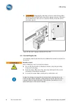
►
WARNING!
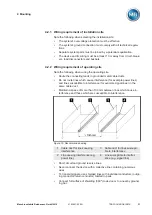
Engaging the assembly to the cap rail at the specified
location while ensuring that the assembly engages correctly. Otherwise
an electrical shock can occur as a result of a faulty connection to the
protective ground.
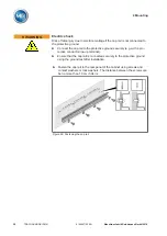
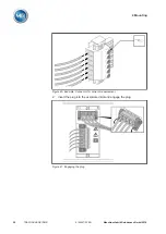
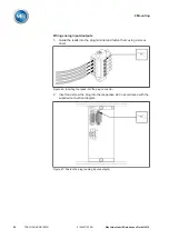
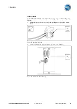
Figure 28: Example: Engaging assemblies DIO and SW
Connecting device
The following section describes how to establish the electrical connection to
the device.
WARNING
Electric shock
Risk of fatal injury due to connection mistakes
► Ground the device with a protective conductor using the grounding
screw on the housing.
► Note the phase difference of the secondary terminals for the current
transformer and voltage transformer.
► Connect the output relays correctly to the motor-drive unit.
Supply the voltage via separators and ensure that current paths can be
short circuited. Fit the separator, clearly labeled, near the device's power
supply so that it is freely accessible. This will allow the device to be re-
placed with ease in the event of a defect.
4.6
Summary of Contents for TRAFOGUARD ISM
Page 1: ...Monitoring System TRAFOGUARD ISM Operating Instructions 5163667 00 EN ...
Page 222: ......
Page 223: ......

