background image

page 18 — MQS36H SeRIeS WaLK-BeHIND TROWeL • OpeRaTION aND paRTS MaNUaL — Rev. #0 (03/08/12) 

7.  Adjustment  of  the  throttle  cable  tension  may  be 

required. If so, loosen the 

adjusting nut 

(top nut)


on 

the  throttle  cable  receiver  (Figure  7)  and  loosen  or 

tighten  the 

locking  nut 

(bottom  nut).  Retighten 

adjusting nut

.

Figure 7. Throttle Cable Receiver Adjustment

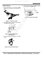
Safety Stop Switch Connection

1.  Connect the black tail wire from the engine to the black 

safety stop wire from the centrifugal stop switch as 

shown in Figure 8.

Figure 8. Safety Stop Switch Connection

pitch Cable Installation

1.  For 

Standard Handle

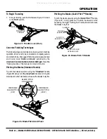
 models expose the pitch cable 

to  maximum  by  turning  the  blade  pitch  star  wheel 

(Figure 9) fully counterclockwise for no pitch (blades 

flat).

Figure 9.  Blade Pitch Star Wheel 

          (Standard Handle)

ADJUSTING

NUT (TOP)

LOCKING NUT

(BOTTOM)

 NOTICE

If  the  throttle  lever  does  not  return  to  the  "neutral" 

position with throttle backed off, loosen adjuster nut 1/2 

turn at a time, tighten and recheck. Readjust throttle 

tension as necessary.

SAFETY STOP WIRE

CONNECTION POINT

INCREASE

BLADE PITCH

(CW)

DECREASE

BLADE PITCH

(CCW)

asseMbly and installatiOn

2.  For 

Quick Pitch™ Handle

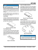
 models expose the pitch 

cable to maximum by grasping the T-handle (Figure 10), 

then  squeezing  the  trigger  lock  and  pushing  the 

T-handle forward for no pitch (blades flat).

Figure 10. Blade Pitch T-Handle 

(Quick Pitch™ Handle)

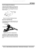
3.  Remove brass set nut #1 from the blade pitch cable 

end as shown in (Figure 11).

Figure 11. Blade Pitch Cable

4.  Thread brass set nut #2 (Figure 11) towards the cable 

as far as possible.

5.  Insert  the  cable  end  through  the  yoke  eyelet 

(Figure 12). Tighten brass set nut #1 by hand to remove 

all the slack from the cable.

T-HANDLE

TRIGGER

(SQUEEZE)

NO PITCH

FORWARD

BLADE

PITCH

CABLE

BRASS SET

NUT #1

BRASS SET

NUT #2

All manuals and user guides at all-guides.com

Summary of Contents for MQS36H55

Page 1: ... To find the latest revision of this publication visit our website at www multiquip com MODEL mqs36h55 MODEL mqs36h90h walk behind trowel HONDA GX160UT1QX2 GX270UTQA2 GASOLINE ENGINES Revision 0 03 08 12 PN 22902 All manuals and user guides at all guides com a l l g u i d e s c o m ...

Page 2: ... are Leadfromlead basedpaints Crystallinesilicafrombricks Cementandothermasonryproducts Arsenicandchromiumfromchemically treatedlumber Your risk from these exposures varies dependingonhowoftenyoudothistype of work To reduce your exposure to these chemicals work in a ALWAYS well ventilated area and work with approved safety equipment such as dust masks that are specially designed to filter out micr...

Page 3: ... defects or other reproductive harm If you are unfamiliar with the risks associated with the particular process and or material being cut or the composition of the tool being used review the material safety data sheet and or consult your employer the material manufacturer supplier governmental agencies such as OSHA and NIOSH and other sources on hazardous materials California and some other author...

Page 4: ... 15 Engine Components 16 Assembly and Installation 17 18 Inspection 19 21 Operation 21 26 Options 27 28 Maintenance 29 37 Troubleshooting 38 41 Wiring Diagram 42 Explanation Of Code In Remarks Column 44 Suggested Spare Parts 45 Component Drawings Nameplate and Decals Assembly 46 47 Standard Handle Assembly 48 49 Quick Pitch Handle Assembly Option 50 51 Guard Assembly 52 53 Gearbox Assembly 54 55 E...

Page 5: ... of engine oil level 3 Fuel system refueling procedure 4 Operation of controls machine not running 5 Safety controls safety stop switch operation 6 Emergency stop procedures 7 Startup of machine engine choke 8 Maintaining a hover 9 Maneuvering 10 Pitching 11 Concrete finishing techniques 12 Shutdown of machine 13 Lifting of machine lifting bale 14 Machine transport and storage All manuals and user...

Page 6: ...parts manUAL rev 0 03 08 12 daily pre operation checklist Daily pre Operation Checklist 1 Engine oil level 2 Condition of blades 3 Blade pitch operation 4 Safety stop switch operation All manuals and user guides at all guides com a l l g u i d e s c o m ...

Page 7: ...with safety messages Warning decals associated with the operation of this equipment are defined below Inhaling exhaust fumes can result in severe injury or death Only operate equipment in well ventilated areas inhale exhaust gases fumes DO NOT WARNING Lethal Exhaust Gas Hazard HOT PARTS can burn skin CAUTION Burn Hazard touch hot parts Allow machine a sufficient amount of time to cool before perfo...

Page 8: ...ea when the equipment is in operation DO NOT use the equipment for any purpose other than its intended purposes or applications NOTICE This equipment should only be operated by trained and qualified personnel 18 years of age and older Whenever necessary replace nameplate operation and safety decals when they become difficult read Manufacturer does not assume responsibility for any accident due to ...

Page 9: ...a running machine NeveR place your feet or hands inside the guard rings while starting or operating this equipment DANGEROUS GAS FUMES NOTICE aLWayS keep the machine in proper running condition Fix damage to machine and replace any broken parts immediately aLWayS store equipment properly when it is not being used Equipment should be stored in a clean dry location out of the reach of children and u...

Page 10: ...tilated areas and away from sparks and flames NeveR use fuel as a cleaning agent DO NOT smoke around or near the equipment Fire or explosion could result from fuel vapors or if fuel is spilled on a hot engine TRaNSpORTINg SaFeTy CaUTION NeveR allow any person or animal to stand underneath the equipment while lifting NOTICE Some walk behind trowels can be lifted or moved by two people utilizing lif...

Page 11: ...o a recycling center Metal recycling involves the collection of metal from discarded products and its transformation into raw materials to use in manufacturing a new product Recyclers and manufacturers alike promote the process of recycling metal Using a metal recycling center promotes energy cost savings eMISSIONS INFORMaTION NOTICE The gasoline engine used in this equipment has been designed to ...

Page 12: ...s kg MQS36H55 Shipping Weight lbs kg MQS36H90H 225 102 235 107 1 Sound pressure is A weighted Measured at the operators ear position while the walk behind trowel is operating at full throttle on concrete in a manner most often experienced in normal circumstances Sound pressure may vary depending upon the condition of the concrete Hearing protection is always recommended 2 The vibration level indic...

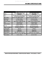
Page 13: ...uel Tank Capacity Approx 0 95 U S Gallons 3 6 Liters Approx 1 95 U S Gallons 6 0 Liters Fuel Unleaded Gasoline Unleaded Gasoline Lube Oil Capacity 0 63 qt 0 6 liters 1 06 qt 1 1 liters Oil Type 4 Stroke API SF or SG SAE 10W 30 General Use 4 Stroke API SF or SG SAE 10W 30 General Use Speed Control Method Centrifugal Fly weight Type Centrifugal Fly weight Type Cooling System Forced Air Forced Air St...

Page 14: ...al manual disappear or otherwise become unusable Drive System Power is transferred from the engine to the gearbox input shaft via a V belt pulley drive system The pulley engages using a centrifugal clutch See parts section of this manual for a breakdown of the drive system Gearbox The gearbox is located beneath the engine and transfers power to the spider assembly The gearbox controls the rotation...

Page 15: ...ome worn or damaged 9 Handlebar Adjuster Change the angle height of the handle bars by loosening star wheel adjust handlebars to desired location tighten starwheel firmly to hold handlebars in that position 10 Centrifugal Kill Switch In the event the operator loses control of the trowel this switch will shut down the engine 11 Blades This trowel is equipped with combination blades These blades are...

Page 16: ...has had an opportunity to cool down In the event of a fuel spill DO NOT attempt to start the engine until the fuel residue has been completely wiped up and the area surrounding the engine is dry 6 Air Cleaner Prevents dirt and other debris from entering the fuel system Remove wing nut on top of air filter canister to gain access to filter element 7 Spark Plug Provides spark to the ignition system ...

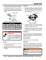
Page 17: ...le cable through the cable housing 3 Connect the trowel throttle cable to the engine throttle linkage Figure 6 There should be a piece of wire installed on the trowel to show where to route the throttle cable 4 Route cable end through the idle control spring and swivel stop When connecting the cable housing make sure that no more than 1 4 6 4 mm of the cable housing protrudes past the housing clam...

Page 18: ...UT BOTTOM NOTICE If the throttle lever does not return to the neutral position with throttle backed off loosen adjuster nut 1 2 turn at a time tighten and recheck Readjust throttle tension as necessary SAFETY STOP WIRE CONNECTION POINT INCREASE BLADE PITCH CW DECREASE BLADE PITCH CCW assembly and installation 2 For Quick Pitch Handle models expose the pitch cable to maximum by grasping the T handl...

Page 19: ...TOR FINISH 48 COMBO FINISH J COMBO FINISH J COMBO FIN ISH 36 CO MB O PR ELO AD TR IM IN D IC ATO R FIN ISH 48 CO MB O FIN ISH J CO MB O FIN ISH J CO MB O ALIGNMENT DECAL 4 Align the groove on the slider with the text 36 COMBO J COMBO on the decal The letter J stands for J 36 Walk Behind Trowel Before Starting 1 Read all safety instructions at the beginning of manual 2 Clean the trowel removing dir...

Page 20: ...e 16 This plug will be marked by the check decal The correct level of the lubrication oil should be to the bottom of the fill plug Figure 16 Gearbox 2 If lubrication oil begins to seep out as the drain plug is being removed then it can be assumed that the gearbox has a sufficient amount of oil 3 If lubrication oil does not seep out as the drain plug is being removed fill with type ISO 680 P N 1013...

Page 21: ...ersonal injury could be caused by dropping a trowel CENTRIFUGAL SAFETY STOP SWITCH ON OFF WARNING NEVER attempt to lift this machine alone NEVER lift the trowel by the guard ring as it may rotate and cause injury ALWAYS make certain the handle is secure and use only the manufacturer s approved lifting point The trowel may be lifted at the center lifting bale by crane or other lifting device of ade...

Page 22: ...ll the throttle lever Figure 20 backwards and place in the idle position Figure 20 Throttle Idle Position THROTTLE LEVER IDLE operation 3 Place the centrifugal safety STOP switch Figure 21 in the ON position Figure 21 Centrifugal Safety Stop Switch ON 4 Place the choke lever Figure 22 in the OPEN position Figure 22 Choke Lever Open ON OFF CENTRIFUGAL SAFETY STOP SWITCH CAUTION NEVER disable or dis...

Page 23: ...se guard ring and or covers operation Testing the Centrifugal Safety Stop Switch 1 With the engine running at idle place the safety stop switch lever in the OFF position Figure 25 Verify that the engine shuts off If the engine continues to run replace centrifugal safety stop switch Figure 25 Testing Safety Stop Switch 2 Before performing this test clear the area around the trowel Make sure it is f...

Page 24: ...ual for more information Pitching the Blades Standard Handle To pitch the blades upwards using the Standard handle Figure 28 simply turn the star wheel clockwise Turning the star wheel counter clockwise will cause the blades to lay flat Figure 28 Blade Pitch Star Wheel THROTTLE LEVER RUN INCREASE BLADE PITCH CW DECREASE BLADE PITCH CCW BLADE PITCH STAR WHEEL operation Pitching the Blades Quick Pit...

Page 25: ...irm grasp on the handle slowly increase the engine speed until the desired blade speed is obtained 2 Figure 30 below illustrates a typical walk behind trowel application Practice maneuvering the trowel The trick is to let the trowel do the work 3 Continue to practice maneuvering the trowel Try to practice as if you were finishing a slab of concrete Practice edging and covering a large area Remembe...

Page 26: ...the engine cools turn the engine start stop switch to the OFF position Figure 32 Figure 32 Engine ON OFF Switch OFF Position 3 Place the safety stop switch Figure 33 in the OFF position Figure 33 Safety Stop Switch OFF THROTTLE LEVER IDLE OFF operation 4 Close the fuel shut off valve Figure 34 by moving the fuel valve lever to the OFF position Figure 34 Fuel Valve Lever OFF All manuals and user gu...

Page 27: ...used after the concrete has set to the point where the trowel does not sink into the concrete when placed on it Figure 36 Finish Blade NOTICE Trowel blades should be changed when they fail to finish concrete in a satisfactory manner Clip On Float Blades Optional These blades will clip Figure 37 onto an existing installed blade allowing your finisher to float on wet concrete so that the troweling o...

Page 28: ... Fixture P N is 1817 Figure 39 Trowel Arm Adjustment Fixture Quick Pitch Handle Optional This feature Figure 40 is not standard equipment on this model walk behind trowel To order this feature please contact MQ unit sales Figure 40 Quick Pitch Handle Option The Quick Pitch Handle feature allows the operator to adjust the pitch of the blades by grasping the handle then squeezing the trigger lever a...

Page 29: ...when used in DUSTY areas 2 These items should be serviced by your service dealer unless you have the proper tools and are mechanically proficient Refer to the HONDA Shop Manual for service procedures 3 For commercial use log hours of operation to determine proper maintenance intervals Table 5 Trowel Maintenance Schedule ITEM OPERATION DAILY Periodic Maintenance Interval Every 50 60 Hrs Every 200 3...

Page 30: ...ay require the engine to be run Ensure that the maintenance area is well ventilated Gasoline engine exhaust contains poisonous carbon monoxide gas that can cause unconsciousness and may result in DEATH Engine Air Cleaner This engine is equipped with a replaceable high density paper air cleaner element See Figure 41 for air cleaner components 1 Remove the air cleaner cover and foam filter element 2...

Page 31: ...vent cross threading then tighten securely NOTICE Operating the engine with loose or damaged air cleaner components could allow unfiltered air into the engine causing premature wear and failure NOTICE NEVER use a spark plug of incorrect heat range maintenance Figure 43 Spark Plug Gap V belt Visually examine the V belt Figure 44 and determine if it is full of tiny cracks frayed has pieces of rubber...

Page 32: ...he thrust collar The goal of the adjustment is to promote consistent blade pitch and finishing quality Adjustments are made by tightening or loosening the blade pitch adjustment bolt Figure 47 Blade Pitch Adjustment Bolt Watch for the following indications when determining if blade pitch adjustments are necessary Is the machine wearing out blades unevenly i e one blade is completely worn out while...

Page 33: ...g operations 5 If after making blade pitch adjustments the machine is still finishing poorly blades trowel arms and trowel arm bushings may be suspect and should be looked at for adjustment wear or damage 6 Figure 49 illustrates incorrect alignment worn spider bushings or bent trowel arms Figure 49 Incorrect Spider Plate Alignment GEARBOX TROWEL ARM MOUNTING BAR BLADE STEEL TEST SURFACE LOWER WEAR...

Page 34: ... properly seat the new blades 4 Install the new blades maintaining the proper blade orientation for direction of rotation 5 Reinstall the bolts and lock washers TROWEL ARM BLADE ATTACHMENT SCREWS TROWEL BLADE BLADE ATTACHMENT BAR maintenance Trowel arm removal 1 Each trowel arm is held in place at the spider plate by a hex head bolt zerk grease fitting and a roll pin Remove both the hex head bolt ...

Page 35: ...URFACE FEELER GAUGE 004 IN 0 10 MM FEELER GAUGE 005 IN 0 127 MM trowel arm Lever adjustment The easiest and most consistent way to adjust the trowel arm lever is to use the Trowel Arm Adjustment Fixture P N 1817 As each trowel arm is locked into the fixture the arm bolt is adjusted to where it contacts a stop on the fixture This will consistently adjust all of the trowel arms keeping the finisher ...

Page 36: ... is little or no lateral movement between the thrust collar and the spider shaft 11 Carefully lift the upper trowel assembly line up the keyway on gear box main shaft and insert into spider assembly 12 Reinstall square head cone point into spider plate and tighten in place Tighten jam nut Use care in making sure point of set screw engages groove in gear box main shaft 13 Lubricate all grease point...

Page 37: ...until the gasoline in the carburetor is completely consumed Completely drain the oil from the crankcase and refill with fresh oil Remove the spark plug Pour 5 to 10 cc of SAE 30 oil into the cylinder Turn the engine switch to the START position for a few seconds to distribute the oil Reinstall the spark plug Clean all external parts of the trowel with a cloth Cover the trowel and store in a clean ...

Page 38: ...lt to start fuel is available and spark is present at the spark plug ON OFF switch is shorted Check switch wiring replace switch Ignition coil defective Replace ignition coil Improper spark gap points dirty Set correct spark gap and clean points Condenser insulation worn or short circuiting Replace condenser Spark plug wire broken or short circuiting Replace defective spark plug wiring Difficult t...

Page 39: ...malfunctions if applicable Recoil mechanism clogged with dust and dirt Clean recoil assembly with soap and water Spiral spring loose Replace spiral spring Starter malfunctions Loose damaged wiring Ensure tight clean connections on battery and starter Battery insufficiently charged Recharge or replace battery Starter damaged or internally shorted Replace starter Burns too much fuel Over accumulatio...

Page 40: ...re no less than 2 50mm from the blade bar to the trailing edge combo blades should measure no less that 3 5 89mm Trailing edge of blade should be straight and parallel to the blade bar Pitch adjustment Check that all blades are set at the same pitch angle as measured at the spider A field adjustment tool is available for height adjustment of the trowel arms Contact Parts Dept Bent trowel arms Chec...

Page 41: ...tion in manual Clutch slipping or sluggish response to engine speed change Worn V belts Replace V belt Hand clutch out of adjustment Adjust per instructions in maintenance section of this manual Worn or defective hand clutch parts Replace parts as necessary Worn bearings in gearbox Rotate input shaft by hand If shaft rotates with difficulty check the input and output shaft bearings Replace as nece...

Page 42: ...v 0 03 08 12 ON OFF CENTRIFUGAL STOP SWITCH OIL LEVEL SWITCH GRN OIL ALERT UNIT YEL OIL LEVEL INDICATOR ENGINE STOP SWITCH UNIT IGNITION COIL CHASSIS GND SPARK PLUG BLK BLK YEL BLK TRANSISTORIZED IGNITION UNIT WIRING DIAGRAM All manuals and user guides at all guides com ...

Page 43: ...MQS36H SERIESWALK BEHINDTROWEL operatION And parts manual rev 0 03 08 12 page 43 notes All manuals and user guides at all guides com ...

Page 44: ...availability of the parts listed NOTICE When ordering a part that has more than one item number listed check the remarks column for help in determining the proper part to order QTy Column Numbers Used Item quantity can be indicated by a number a blank entry or A R A R As Required is generally used for hoses or other parts that are sold in bulk and cut to length A blank entry generally indicates th...

Page 45: ... 0152 3 V BELT A 28 mqs36h55 2 1243 V BELT A 27 mQS36H90 2 10139 GEARBOX LUBRICANT 1 22732 THROTTLE LEVER ASSY NOTICE Part numbers on this Suggested Spare Parts list may supersede replace the part numbers shown in the following parts lists HONDA GX160UT1QX2 Qty P N Description 3 9807955876 SPARK PLUG 1 17620Z4H020 TANK CAP 3 17210ZE1822 AIR CLEANER ELEMENT 3 17218ZE1821 FILTER OUTER 1 28462ZH8003 ...

Page 46: ...L NO 3 7 9 4 P N 36099 1 2 5 10 P N 23700 WWW MULTIQUIP COM WALK BEHIND POWER TROWEL 6 8 FINISH J COMBO PRELOAD TRIM INDICATOR FINISH B COMBO STANDARD HANDLE QUICK PITCH HANDLE 11 P N 23700 WWW MULTIQUIP COM WALK BEHIND POWER TROWEL P N 36099 12 All manuals and user guides at all guides com a l l g u i d e s c o m ...

Page 47: ...TING CRUSH 2 4 X 2 0 1 4 36099 ISO DECAL PROTECTIVE CLOTHING 3 50 X 1 13 1 5 23701 ISO DECAL ASK FOR TRAINING 2 00 DIA 1 6 23702 DECAL MQ LOGO 12 30 X 1 457 1 7 20816 DECAL MQ LOGO 6 78 X 80 1 8 23683 DECAL SERIAL PLATE WBT CHINA 1 9 23703 DECAL MQ MULTIQUIP ROUND 3 78 DIA 1 10 23704 ISO DECAL GUARD WARNING 2 00 DIA 1 11 1735 DECAL PRE LOAD 1 QUICK PITCH ONLY 12 22897 MQS DECAL KIT 1 INCLUDES ITEM...

Page 48: ...ROWEL operation and parts manUAL rev 0 03 08 12 STANDARD HANDLE ASSY 14 13 2 22 9 16 6 15 24 25 21 5 7 11 12 20 23 19 18 17 4 3 1 27 28 10 26 37 32 29 30 33 31 8 34 34 35 36 IN STRUCTIO NS All manuals and user guides at all guides com ...

Page 49: ...2 THROTTLE BICYCLE FINISHER HANDLES 1 18 21172 CABLE THROTTLE 68 1 19 21173 HOUSING MAGURA THROTTLE CABLES 1 20 22055 HANDLE WA VIBRATION CONTROL 1 21 22059 ISOLATOR VIB 80 DUROMETER SHORE A 3 22 22095 HANDLE W A STOW FIN VIBE CONTROL 1 23 22166 COVER VIBE CONTROL HANDLE PAD 1 24 22167 SCREW HHC 3 8 16 X 6 5 GRADE 5 1 25 22206 CHASSIS CAST VIBRATION ISOLATOR 1 REPLACES P N 22056 26 22100 KIT VIBE ...

Page 50: ... manUAL rev 0 03 08 12 quick pitch HANDLE ASSY option 30 22 24 3 20 35 51 46 31 28 32 13 33 2 14 29 11 19 4 8 48 49 5 10 9 15 23 16 21 1 26 25 27 40 18 6 36 47 37 38 34 7 39 17 12 41 42 43 44 45 50 IN S TR UCTIO NS All manuals and user guides at all guides com ...

Page 51: ...7 SCREW HHC 3 8 16 X 3 25 FULL THRD GR5 1 24 21171 THROTTLE LEVER 1 25 21172 CABLE THROTTLE 68 1 26 21173 HOUSING MAGURA THROTTLE CABLES 1 27 20297 CABLE ASM LENGTH 45 JB HD QP 1 28 22055 HANDLE WA VIBRATION CONTROL 1 29 22059 ISOLATOR VIB 80 DUROMETER SHORE A 3 30 22060 MAIN HANDLE WA QP VIBE CONTROL 1 31 22166 COVER VIBE CONTROL HANDLE PAD 1 32 22167 SCREW HHC 3 8 16 X 6 5 GRADE 5 1 33 22206 CHA...

Page 52: ...page 52 MQS36H SERIESWALK BEHINDTROWEL operation and parts manUAL rev 0 03 08 12 GUARD ASSY 10 1 11 12 9 8 7 6 2 3 4 5 All manuals and user guides at all guides com ...

Page 53: ...4 22024 SCREW HHC 5 16 24 X 1 3 4 GR5 ZINC 4 MQS36H55 4 10181 SCREW HHC 5 16 24 X 1 1 4 GR5 ZINC 4 MQS36H90H 5 933241 WASHER FLAT SAE 5 16 GRD 9YZ 4 6 21880 ACCESS PANEL M J GUARD RING 1 7 26250 SCREW HHC 1 4 20 X 1 3 4 2 8 21893 SCREW FAST LEAD 1 9 21986 WASHER FAST LEAD STAINLESS 1 10 21894 CLIP FAST LEAD 1 11 21922 CLAMP 0 625 ID PIPE 2 12 10024 NUT NYLOC 1 4 20 2 GUARD ASSY All manuals and use...

Page 54: ...2 APPLY THREAD LOCK LOCTITE 572 WHITE P N 60096 OR EQUIVALENT 3 TORQUE TO 15 FT LBS 20 Nm 4 GASKETS ARE NOT SOLD SEPARATELY SHIM GASKETS AS NECESSARY FOR INPUT SHAFT END PLAY 5 GASKETS ARE NOT SOLD SEPARATELY SHIM GASKETS AS NECESSARY FOR OUTPUT SHAFT END PLAY 6 USE SPECIALLY FORMULATED WHITEMAN GEARBOX LUBRICANT P N 10139 OR ISO OIL GEARBOX REQUIRES 26 OZ 0 8 LITERS OF GEARBOX LUBRICANT FOR OPERA...

Page 55: ...20476 SCREW HHC 1 4 28 X 3 8 2 15 21033 SIGHT GLASS 3 4 M PIPE STEEL 1 16 0121 A FITTING PLUG 3 8 MP SQ HEAD 1 17 1138 RING SNAP TRUARC 5100 112 1 18 20475 BEARING CUP TIMKEN M86610 2 19 20474 BEARING CONE TIMKEN M86647 2 20 1140 GEAR WORM COMPOSITE 1 21 20470 SHAFT OUTPUT 1 22 1139 KEY WOODRUFF 810 1 23 1238 KEY WOODRUFF 25 1 25 20396 O RING 254 BUNA N 1 26 12875 COVER GEARBOX 1 27 10235 WASHER C...

Page 56: ...8 19 14 8 2 5 12 11 10 9 4 4 4 21 22 31 3 13 26 30 29 25 27 28 6 1 20 NOTES APPLY BLUE LOCTITE 246 ITEM 23 1 1 BLUE LOCTITE 23 1 1 LOW SPEED KIT 2 FOR OPTIMUM PANNING PERFORMANCE BLADE SPEED MUST BE CHANGED USE LOW SPEED KIT ITEM 31 2 All manuals and user guides at all guides com a l l g u i d e s c o m ...

Page 57: ... 0152 3 V BELT A28 1 5 5 HP MQS36H55 PANS 11 1243 V BELT A27 1 9 0 HP MQS36H90H 12 21970 BELT GUARD 1 13 0253 CLUTCH PLATE 1 14 1868 SCREW SHS 3 8 24 X 3 4 NP 2 15 0855 SPRING CLUTCH 156 X 5 375 X 025 1 16 B1766 WEIGHT AUTOMATIC CLUTCH 4 17 0251 DRUM CENTRIFUGAL CLUTCH 1 18 0456 BEARING SHIELDED 6007 ZZ E 1 19 21307 CLUTCH SPINDLE 3 4 BORE 1 5 5 HP MQS36H55 19 0252 CLUTCH SPINDLE 1 BORE 1 9 0 HP M...

Page 58: ... INCLUDES ALL ITEMS WITHIN OUTLINE APPLY LOCTITE P N 1477 TO ITEMS 1 AND 14 NOTES 2 3 INCLUDED WITH ITEM 19 OR CAN BE ORDERED SEPARATELY P N 1471 TORQUE TO 90 FT LBS 122 Nm TORQUE TO 130 FT LBS 176 Nm 1 25 17 18 19 20 3 21 4 5 13 11 1 2 14 7 9 10 5 8 4 3 15 6 12 24 22 4 23 5 16 All manuals and user guides at all guides com ...

Page 59: ... 3 8 16 1 10 1875 WASHER INT SHKP 3 8 4 11 1876 NUT HEX JAM 3 8 16 CLASS 2B 4 12 2826 ARM J FINISHER EXTENDED 4 13 4164 ROLL PIN 5 16 x 1 3 4 4 14 12097 SCREW SQHS 3 8 16 X 1 3 4 CONE GRD 8 1 15 1215 SPIDER PLATE ASSY 1 INCLUDES ITEMS W 16 10968 THRUST BEARING KIT 1 INCLUDES ITEMS W 17 12208 WEAR RING 1 18 12778 FLANGE BEARING 1 19 10793 THRUST COLLAR 1 INCLUDES ITEMS W 20 1471 THRUST COLLAR BUSHI...

Page 60: ...page 60 MQS36H SERIESWALK BEHINDTROWEL operation and parts manUAL rev 0 03 08 12 BLADE ASSY 8 1 3 6 5 9 17 16 18 10 12 11 15 14 7 5 All manuals and user guides at all guides com ...

Page 61: ... SUPER FLAT 1 8 CL945 FLOAT BLADE 10X14 CLIP ON 4 9 F10900 ENDURO FINISH BLADE 6X14 4 10 C10844 ENDURO COMBO BLADE 8X14 4 11 QF1872 QUICK CHANGE BLADE 6X14 4 11 QF10872 ENDURO QUICK CH FINISH BLADE 6X14 4 12 QC1871 QUICK CHANGE COMBO BLADE 8X14 4 12 QC10871 ENDURO QK CHNG COMBO BLADE 8X14 4 14 QB1857 UNIVERSAL MOUNTING BAR 4 15 QS1869 SNAP PIN 1 4 X1 3 4 8 16 1434 TROWEL LUG FINISH BLADE ONLY 4 17...

Page 62: ...page 62 MQS36H SERIESWALK BEHINDTROWEL operation and parts manUAL rev 0 03 08 12 Engine ASSY 1 2 3 4 5 All manuals and user guides at all guides com ...

Page 63: ...0 TANK CAP 1 2 28462ZH8003 ROPE RECOIL 1 gx160ut1qx2 2 28462ZE2W11 ROPE RECOIL 1 gx270utqa2 3 17210ZE1822 AIR CLEANER ELEMENT 1 GX160UT1QX2 3 17210ZE2822 AIR CLEANER ELEMENT 1 GX270UTQA2 4 17218ZE1821 FILTER OUTER 1 GX160UT1QX2 4 17218ZE2821 FILTER OUTER 1 GX270UTQA2 5 9807955876 SPARK PLUG 1 All manuals and user guides at all guides com ...

Page 64: ...he property of their respective owners and used with permission This manual MUsT accompany the equipment at all times This manual is considered a permanent part of the equipment and should remain with the unit if resold The information and specifications included in this publication were in effect at the time of approval for printing Illustrations descriptions references and technical data contain...

Reviews: