background image

ioLogik E1200 Series 

Initial Setup 


2-3 

Jumper Settings   

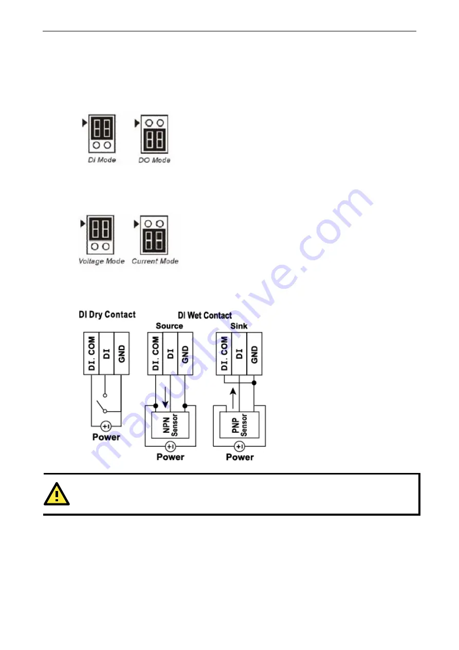
The ioLogik E1212, E1240, and E1242 require configuring the jumpers inside the enclosure. Remove the screw 
on the back panel and open the cover to configure the jumpers. 

DIO mode configuration is as follows (default is DO Mode) 


Analog mode configuration is as follows (default is Voltage Mode) 


I/O Wiring Diagrams 


ATTENTION 

Remove the screw on the back panel and open the cover to configure the jumpers.


Summary of Contents for ioLogik E1200 Series

Page 1: ...ioLogik E1200 Series User s Manual Fifth Edition February 2011 www moxa com product 2011 Moxa Inc All rights reserved Reproduction without permission is prohibited ...

Page 2: ... reserves the right to make improvements and or changes to this manual or to the products and or the programs described in this manual at any time Information provided in this manual is intended to be accurate and reliable However Moxa assumes no responsibility for its use or for any infringements on the rights of third parties that may result from its use This product might include unintentional ...

Page 3: ...defined Modbus Addressing 3 4 Default Address 3 4 AOPC Server Settings 3 5 I O Settings 3 5 DI Channels 3 5 DO Channels 3 6 AI Channels 3 7 AO Channels 3 9 RTD Channels 3 10 TC Channels 3 11 System Management 3 12 IP Accessibility 3 12 Network Connection 3 13 Firmware Update 3 13 Import System Config 3 13 Export System Config 3 13 Peer to peer Settings 3 14 Peer to peer Settings 1 50 3 14 Sample C...

Page 4: ...inks 5 5 Tag Generation 5 5 Heartbeat Interval 5 6 Read Write Privilege 5 7 OPC Test Client 5 7 A Modbus TCP Default Address Mappings A 1 E1210 Modbus Mapping A 2 E1211 Modbus Mapping A 4 E1212 Modbus Mapping A 5 E1214 Modbus Mapping A 9 E1240 Modbus Mapping A 11 E1241 Modbus Mapping A 11 E1242 Modbus Mapping A 12 E1260 Modbus Mapping A 14 E1262 Modbus Mapping A 14 B Network Port Numbers B 1 C Fac...

Page 5: ... connect sensors and on off switches for automation applications over Ethernet and IP based networks The following topics are covered in this chapter Product Model Information Product Features Inside the Box Product Specifications Physical Dimensions Hardware Reference Panel Guide LED Indicators ...

Page 6: ... port Ethernet switch 6 DIs and 6 Relays 40 to 75 C operating temperature ioLogik E1240 T Ethernet remote I O with 2 port Ethernet switch and 8 AIs 40 to 75 C operating temperature ioLogik E1241 T Ethernet remote I O with 2 port Ethernet switch and 4 AOs 40 to 75 C operating temperature ioLogik E1242 T Ethernet remote I O with 2 port Ethernet switch 4 AIs 4 DIs and 4 DIOs 40 to 75 C operating temp...

Page 7: ...1 Digital Output I O Mode DO or Pulse Output Pulse Wave Width Frequency 1 ms 500 Hz Over voltage Protection 45 VDC Over current Protection 2 6 A 4 channels 650 mA Over temperature Shutdown 175 C typical 150 C min Current Rating 200 mA per channel Isolation 3K VDC or 2K Vrms Power Requirements Power Consumption 208 mA 24 VDC MTBF meantime between failures Time 221 662 hrs Database Telcordia Bellcor...

Page 8: ...GND Logic 1 open Wet Contact Logic 0 0 to 3 VDC Logic 1 10 to 30 VDC DI COM to DI Isolation 3K VDC or 2K Vrms Counter Frequency 250 Hz power off storage Relay Output Type Form A N O relay outputs 5A Contact Rating 5 A 30 VDC 5 A 250 VAC 5 A 110 VAC Inductance Load 2 A Resistance Load 5 A Breakdown Voltage 500 VAC Relay On Off Time 1500 ms Max Initial Insulation Resistance 1G min 500 VDC Expected L...

Page 9: ...r Internal power 400 ohms External 24V power 1000 ohms Power Requirements Power Consumption 194 mA 24 VDC MTBF meantime between failures Time 888 656 hrs Database Telcordia Bellcore ioLogik E1242 Analog Input Type Differential input Resolution 16 bits I O Mode Voltage Current Input Range 0 to 10 VDC 4 to 20 mA Accuracy 0 1 FSR 25 C 0 3 FSR 10 and 60 C Sampling Rate all channels 12 samples sec Inpu...

Page 10: ...1000 Resistance of 10 ohms 20 ohms and 100 ohms Sampling Rate 12 samples sec all channels Resolution 16 bits Accuracy 0 1 FSR 25 C 0 3 FSR 10 and 60 C Input Impedance 625K ohms Power Requirements Power Consumption 110 mA 24 VDC MTBF meantime between failures Time 660 260 hrs Database Telcordia Bellcore ioLogik E1262 Thermocouple Input Sensor Type J K T E R S B N Mili Volt Type 78 126 mV 39 062 mV ...

Page 11: ... 60 C 14 to 140 F Wide Temperature Models 40 to 75 C 40 to 167 F Storage Temperature 40 to 85 C 40 to 185 F Ambient Relative Humidity 5 to 95 non condensing Standards and Certifications Safety UL 508 EMI FCC Part 15 Subpart B Class A EMS IEC 61000 4 IEC 61000 6 Shock IEC 60068 2 27 Freefall IEC 60068 2 32 Vibration IEC 60068 2 6 Note Please check Moxa s website for the most up to date certificatio...

Page 12: ...then release the reset button LED Indicators LED State Description Power Amber System power is ON OFF System power is OFF Ready Green System is ready Flashing Flashes every 1 sec when the Locate function is triggered Flashing Flashes every 0 5 sec when the firmware is being upgraded Flashing Cycle on off period of 0 5 sec represents Safe Mode OFF System is not ready Port 1 Green Ethernet connectio...

Page 13: ...install the ioLogik E1200 The following topics are covered in this chapter Hardware Installation Connecting the Power Grounding the ioLogik E1200 Connecting to the Network Jumper Settings I O Wiring Diagrams Software Installation Load Factory Default ...

Page 14: ...nt on the terminal block located on the top panel Connect the ground pin if earth ground is available Connecting to the Network The ioLogik E1200 has two built in Ethernet switch ports for connecting a standard direct or cross over Ethernet cable from RJ45 port to either the host PC or another ioLogik E1200 device For initial setup of the ioLogik E1200 it is recommended that the ioLogik E1200 be c...

Page 15: ...ide the enclosure Remove the screw on the back panel and open the cover to configure the jumpers DIO mode configuration is as follows default is DO Mode Analog mode configuration is as follows default is Voltage Mode I O Wiring Diagrams ATTENTION Remove the screw on the back panel and open the cover to configure the jumpers ...

Page 16: ...ioLogik E1200 Series Initial Setup 2 4 ...

Page 17: ...ately 2 Open ioSearch After installation is finished run ioSearch from Start Program Files MOXA IO Server Utility ioSearch 3 Search the network for the server On the menu bar select System Auto Scan Active Ethernet I O Server A dialog window will pop up Click Start Search to begin searching for the ioLogik E1200 If multiple ioLogik E1200 units are installed on the same network remember that each u...

Page 18: ...ttings Ethernet Configuration User defined Modbus Addressing User defined Modbus Addressing Default Address AOPC Server Settings I O Settings DI Channels DO Channels AI Channels AO Channels RTD Channels TC Channels System Management IP Accessibility Network Connection Firmware Update Import System Config Export System Config Peer to peer Settings Peer to peer Settings 1 50 Sample Configuration DO ...

Page 19: ...making configuration changes The Submit button will be located at the bottom of every page that has configurable settings If you navigate to another page without clicking the Submit button your changes will not be retained Submitted changes will not take effect until they are saved and the ioLogik E1200 is restarted You may save and restart the server in one step by clicking on the Save Restart bu...

Page 20: ...s network connection for the specified amount of time Safe Mode is designed especially for products that have output channels to output a suitable value or status when the ioLogik E1200 cannot be controlled by a remote PC due to network failure for example By default the Watchdog is disabled Users can configure how each output channel responds on the I O Settings page To enable the Watchdog check ...

Page 21: ... page Check the Enable User defined Modbus Addressing box select the Modbus function and then configure the start address of each item ATTENTION Disable the user defined modbus addressing function if using the MXIO NET library or using Active OPC Server to control or monitor the ioLogik E1200 s I O Status Default Address On this settings page you can view the default Modbus address for all I O dev...

Page 22: ...ection in Chapter 5 Active OPC Server Lite I O Settings DI Channels The status of each DI digital input channel appears on the DI Channels page You can also configure each channel s digital input mode and parameters by clicking on the channel DI channels can operate in DI mode or Event Counter mode ...

Page 23: ... digital output channel by clicking on the channel DO Channels can operate in DO mode or Pulse Output mode In DO mode output is either on or off In Pulse Output mode configure the low width and high width to generate a square wave The Power On Setting field is used to specify the channel s configuration when the ioLogik E1200 is powered on and the Safe Status Setting field specifies the channel s ...

Page 24: ... the jumpers for input or output selection of the DIO channels Refer to chapter 2 for detailed jumper settings AI Channels The current status of each AI analog input channel can be viewed on the AI Channels page Click on a specific channel to enable or disable the AI channel by checking the Enable AI Channel box The Auto Scaling and Slope intercept function of the AI value can be defined on this p...

Page 25: ...age or current measurement for the AI channels Refer to chapter 2 for detailed jumper settings The Auto scaling function maps the original AI value linearly to a scaled value Note that the scaled value s Modbus address differs from the original value The slope intercept function is used to compensate when the measurement requires a slight adjustment ...

Page 26: ...nnel page Click on a specific channel to access the AO channel settings and then select the Enable AO Channel box The Auto Scaling function of the AO value can be defined on this page The Auto scaling function maps the original AO output linearly to a scaled value Note that the scaled value s Modbus address differs from the original value ...

Page 27: ...meets the physical attachment to the ioLogik E1200 The ioLogik E1200 allows you to calibrate the temperature sensors In each channel configuration section follow the instructions and click Calibrate button to start the RTD sensor calibration Each calibration requires around 30 seconds per channel The ioLogik E1200 allows you to manually adjust the current temperature reading In each channel config...

Page 28: ...or disabling of the TC channel Select the Enable TC Channel box and then select the sensor type that meets the physical attachment to the ioLogik E1200 The ioLogik E1200 allows you to calibrate the temperature sensors In each channel configuration section follow the instructions and click the Calibrate button to start the TC sensor calibration Each calibration requires about 30 seconds per channel...

Page 29: ... in order to gain access to the ioLogik E1200 Specify a range of addresses by using a combination of an IP address and netmask as follows To allow access to a specific IP address Enter the IP address in the corresponding field enter 255 255 255 255 for the netmask To allow access to hosts on a specific subnet For both the IP address and netmask use 0 for the last digit e g 192 168 1 0 and 255 255 ...

Page 30: ...formation can assist you with managing your devices Firmware Update Load new or updated firmware onto the ioLogik from the Firmware Update page Import System Config Import a configuration into the ioLogik server from the Import System Config page This function can be used to duplicate settings between ioLogik servers You will be prompted for the location of the configuration file i e ik1212 txt Ex...

Page 31: ... Remote Channel field is for you to select input channels of the remote ioLogik E1200 when you select output channels in the Local Channel field Set the Interval Time and On change percentage on the local ioLogik E1200 that will trigger the transmission of a mapping signal to the remote ioLogik E1200 The default local listen port number is 9020 this value can be set between 1 to 65535 NOTE If you ...

Page 32: ...les 40 rules 50 rules DO Safe Mode Settings When a peer to peer rule on a local DO channel is not valid the local DO channel will enter safe mode You can set the DO to be Hold Last ON or OFF in safe mode AO Safe Mode Settings When a peer to peer rule of the local AO channel is not valid the local AO channel will enter safe mode You can either set the AO safe value from 0 4095 or enable Hold Last S...

Page 33: ...rget the password the ONLY way to configure the ioLogik E1200 is by using the reset button to load the factory defaults Before you set a password for the first time it is a good idea to export the configuration to a file when you have finished setting up your ioLogik E1200 Your configuration can then be easily imported back into the ioLogik E1200 if you need to reset the ioLogik E1200 due to a for...

Page 34: ...ocate ioLogik E1200 units The following topics are covered in this chapter Introduction to ioSearch ioSearch Main Screen Main Screen Overview Main Items System Sort Quick Links Main Function Locate Firmware Upgrade Unlock Import Export Change IP Address Restart System Reset to Default ...

Page 35: ... file to multiple ioLogik E1200 units same model Reset to default for multiple ioLogik E1200 units ioSearch Main Screen Main Screen Overview The main screen displays the result of the broadcast search of the ioLogik E1200 ioSearch Main Screen 1 Title 2 Menu bar 3 Quick link 4 Navigation panel 5 Main window Main Items System Several operations are possible from the System menu Auto Scan Active Ethe...

Page 36: ...arch 4 3 Network Interface allows you to select a network to use if the PC has multiple network adaptors installed Sort The Sort menu allows the server list in the navigation panel to be sorted by ioLogik connection and server model ...

Page 37: ...ight click on a particular ioLogik E1200 to view the ioSearch function menu Locate The locate function helps users find a dedicated ioLogik on the network When this function is triggered the ready LED on the selected unit will start to blink indicating its location Firmware Upgrade The ioLogik E1200 supports a remote firmware upgrade function Enter the path to the firmware file or click on the ico...

Page 38: ...Unlock If an ioLogik E1200 is password protected unlock the ioLogik E1200 by entering the password before using any of the functions Import Select this command to reload a configuration that was exported to a text file Importing one configuration file to multiple ioLogik E1200 units same model is allowed To do this press the Shift key select the ioLogik and then right click ...

Page 39: ...ogik E1200 e g ik1214_00 90 E8 66 32 19 txt To export multiple configuration files select the ioLogik and right click to process this function Change IP Address The Change IP Address function can be used to directly modify the IP Address especially for first time installation Changing the IP address for multiple ioLogik E1200 s is allowed Select the ioLogik E1200 and then right click to process th...

Page 40: ... Default Select this function to reset all settings including console password to factory default values Resetting multiple ioLogik E1200 units to the default configuration is allowed Select the ioLogik E1200 and right click to process this function ...

Page 41: ... The following topics are covered in this chapter Introduction to Active OPC Server Lite Active OPC Server Lite Specifications Installing Active OPC Server Lite Installing OPC Core Components Active OPC Server Lite Main Screen Overview Menu Items File System Sort Quick Links Tag Generation Heartbeat Interval Read Write Privilege OPC Test Client ...

Page 42: ...er Installing Active OPC Server Lite Active OPC Server Lite can be found in the Document and Software CD or downloaded from the Moxa Website The following steps show how to install Active OPC Server Lite from the CD 1 Installing from CD Insert the Document and Software CD into the host computer In the Software AOPCLite ActiveOPCSetup directory of the CD locate and run Install exe The installation ...

Page 43: ...n 1 Title 2 Menu bar 3 Quick link 4 Navigation panel 5 Tag Window 6 Log Monitor 7 Status bar Menu Items File From the File menu you can export the list ioLogik units that are currently displayed in the navigation panel You also can import a list into Active OPC Server Lite The file will have the mdb extension and can be opened using Microsoft Office Access The server list includes the current tag ...

Page 44: ...erval of a controlling output channel on a remote ioLogik Register OPC Server is used to register the DCOM components to the Windows system After Active OPC Server Lite is installed it will automatically configure the DCOM Heartbeat Tolerance allows users to define the timeout to wait for a heartbeat signal from a remote ioLogik System Log Settings allows users to enable or disable Active OPC Serv...

Page 45: ...xport configuration Tag Generation Tag configuration of an ioLogik E1200 is specified by its web console Open the browser and go to the Active OPC Server Settings page Follow these steps to create the tag from the ioLogik E1200 to Active OPC Server Lite In the AOPC I O Settings page Check the Enable Active OPC box and specify the IP address where the Active OPC Server Lite is installed Select the ...

Page 46: ...al Tags are event driven and updated only when the status of an I O channel changes When the status remains unchanged the Active OPC Server Lite will not receive updates To ensure that the ioLogik is connected and alive Heartbeat Interval can be used to determine the connection status between the ioLogik and Active OPC Server Lite If the heartbeat interval is set and the network between the ioLogi...

Page 47: ...an be launched from the Windows Start menu Start Program Files MOXA IO Server ActiveOPC ClientTest If Active OPC Server Lite is installed locally on the same PC select Connect Local from the menu bar Specify the MOXA ACTIVE OPC SERVER in the Server Name column If the Active OPC Server Lite is installed on a remote PC select Connect Remote from the menu bar Input the host name i e Moxa_Client or IP...

Page 48: ...E1200 Series Active OPC Server Lite 5 8 Click Item Browse and select the channel that needs to be monitored To write to the output channel specify an output channel and then select Item Write from the menu bar ...

Page 49: ...ioLogik E1200 Series Active OPC Server Lite 5 9 ...

Page 50: ...s The following topics are covered in this appendix E1210 Modbus Mapping E1211 Modbus Mapping E1212 Modbus Mapping E1214 Modbus Mapping E1240 Modbus Mapping E1241 Modbus Mapping E1242 Modbus Mapping E1260 Modbus Mapping E1262 Modbus Mapping ...

Page 51: ...0B 1 bit CH11 DI Counter Operate Status 0 Stop 1 Start R W 00269 0x010C 1 bit CH12 DI Counter Operate Status 0 Stop 1 Start R W 00270 0x010D 1 bit CH13 DI Counter Operate Status 0 Stop 1 Start R W 00271 0x010E 1 bit CH14 DI Counter Operate Status 0 Stop 1 Start R W 00272 0x010F 1 bit CH15 DI Counter Operate Status 0 Stop 1 Start R W 00273 0x0110 1 bit CH0 DI Clear Count Value Read A lways return 0...

Page 52: ...it CH13 DI Clear Count Value Read Always return 0 Write 1 Clear counter value 0 Return illegal data value 0x03 00287 0x011E 1 bit CH14 DI Clear Count Value Read A lways return 0 Write 1 Clear counter value 0 Return illegal data value 0x03 00288 0x011F 1 bit CH15 DI Clear Count Value Read A lways return 0 Write 1 Clear counter value 0 Return illegal data value 0x03 1xxxx Read Only Coils Function 2 ...

Page 53: ...I Counter Value Lo Word Read only 30031 0x001E 1 word CH7 DI Counter Value Hi Word Read only 30032 0x001F 1 word CH7 DI Counter Value Lo Word Read only 30033 0x0020 1 word CH8 DI Counter Value Hi Word Read only 30034 0x0021 1 word CH8 DI Counter Value Lo Word Read only 30035 0x0022 1 word CH9 DI Counter Value Hi Word Read only 30036 0x0023 1 word CH9 DI Counter Value Lo Word Read only 30037 0x0024...

Page 54: ...rate Status 0 Off 1 On 00024 0x0017 1 bit CH7 DO Pulse Operate Status 0 Off 1 On 00025 0x0018 1 bit CH8 DO Pulse Operate Status 0 Off 1 On 00026 0x0019 1 bit CH9 DO Pulse Operate Status 0 Off 1 On 00027 0x001A 1 bit CH10 DO Pulse Operate Status 0 Off 1 On 00028 0x001B 1 bit CH11 DO Pulse Operate Status 0 Off 1 On 00029 0x001C 1 bit CH12 DO Pulse Operate Status 0 Off 1 On 00030 0x001D 1 bit CH13 DO...

Page 55: ...tus 0 Stop 1 Start R W 00270 0x010D 1 bit CH13 DI Counter Operate Status 0 Stop 1 Start R W 00271 0x010E 1 bit CH14 DI Counter Operate Status 0 Stop 1 Start R W 00272 0x010F 1 bit CH15 DI Counter Operate Status 0 Stop 1 Start R W 00273 0x0110 1 bit CH0 DI Clear Count Value Read A lways return 0 Write 1 Clear counter value 0 Return illegal data value 0x03 00274 0x0111 1 bit CH1 DI Clear Count Value...

Page 56: ...l data value 0x03 00288 0x011F 1 bit CH15 DI Clear Count Value Read A lways return 0 Write 1 Clear counter value 0 Return illegal data value 0x03 1xxxx Read Only Coils Function 2 Reference Address Data Type Description 10001 0x0000 1 bit CH0 DI Value 0 OFF 1 ON Read only 10002 0x0001 1 bit CH1 DI Value 0 OFF 1 ON Read only 10003 0x0002 1 bit CH2 DI Value 0 OFF 1 ON Read only 10004 0x0003 1 bit CH3...

Page 57: ...0 1 word CH8 DI Counter Value Hi Word Read only 30034 0x0021 1 word CH8 DI Counter Value Lo Word Read only 30035 0x0022 1 word CH9 DI Counter Value Hi Word Read only 30036 0x0023 1 word CH9 DI Counter Value Lo Word Read only 30037 0x0024 1 word CH10 DI Counter Value Hi Word Read only 30038 0x0025 1 word CH10 DI Counter Value Lo Word Read only 30039 0x0026 1 word CH11 DI Counter Value Hi Word Read ...

Page 58: ...1 DI Counter Operate Status 0 Stop 1 Start R W 00259 0x0102 1 bit CH2 DI Counter Operate Status 0 Stop 1 Start R W 00260 0x0103 1 bit CH3 DI Counter Operate Status 0 Stop 1 Start R W 00261 0x0104 1 bit CH4 DI Counter Operate Status 0 Stop 1 Start R W 00262 0x0105 1 bit CH5 DI Counter Operate Status 0 Stop 1 Start R W 00273 0x0110 1 bit CH0 DI Clear Count Value Read A lways return 0 Write 1 Clear c...

Page 59: ...alue Lo Word Read only 30019 0x0012 1 word CH1 DI Counter Value Hi Word Read only 30020 0x0013 1 word CH1 DI Counter Value Lo Word Read only 30021 0x0014 1 word CH2 DI Counter Value Hi Word Read only 30022 0x0015 1 word CH2 DI Counter Value Lo Word Read only 30023 0x0016 1 word CH3 DI Counter Value Hi Word Read only 30024 0x0017 1 word CH3 DI Counter Value Lo Word Read only 30025 0x0018 1 word CH4...

Page 60: ...i float 30016 0x000F 1 word CH3 Read AI Scaling Value Low float 30017 0x0010 1 word CH4 Read AI Scaling Value Hi float 30018 0x0011 1 word CH4 Read AI Scaling Value Low float 30019 0x0012 1 word CH5 Read AI Scaling Value Hi float 30020 0x0013 1 word CH5 Read AI Scaling Value Low float 30021 0x0014 1 word CH6 Read AI Scaling Value Hi float 30022 0x0015 1 word CH6 Read AI Scaling Value Low float 300...

Page 61: ...0 Stop 1 Start R W 00262 0x0105 1 bit CH5 DI Counter Operate Status 0 Stop 1 Start R W 00263 0x0106 1 bit CH6 DI Counter Operate Status 0 Stop 1 Start R W 00264 0x0107 1 bit CH7 DI Counter Operate Status 0 Stop 1 Start R W 00273 0x0110 1 bit CH0 DI Clear Count Value Read A lways return 0 Write 1 Clear counter value 0 Return illegal data value 0x03 00274 0x0111 1 bit CH1 DI Clear Count Value Read A...

Page 62: ...rd Read only 30021 0x0014 1 word CH2 DI Counter Value Hi Word Read only 30022 0x0015 1 word CH2 DI Counter Value Lo Word Read only 30023 0x0016 1 word CH3 DI Counter Value Hi Word Read only 30024 0x0017 1 word CH3 DI Counter Value Lo Word Read only 30025 0x0018 1 word CH4 DI Counter Value Hi Word Read only 30026 0x0019 1 word CH4 DI Counter Value Lo Word Read only 30027 0x001A 1 word CH5 DI Counte...

Page 63: ...ange 0 65535 Unit 0 1 Ohm Celsius Fahrenheit E1262 Modbus Mapping 3xxxx Read Only Registers Function 4 Reference Address Data Type Description 32049 0x0800 1 word CH0 TC Minimum Value Hi Word Unit 0 1 Celsius Fahrenheit 0 0001 mV 32050 0x0801 1 word CH0 TC Minimum Value Lo Word Hi Lo Range 0 4294967295 Unit 0 1 Celsius Fahrenheit 0 0001 mV 32051 0x0802 1 word CH1 TC Minimum Value Hi Word 32052 0x0...

Page 64: ...ioLogik E1200 Series Modbus TCP Default Address Mappings A 15 32065 0x0810 1 word CH8 TC Minimum Value Hi Word 32066 0x0811 1 word CH8 TC Minimum Value Lo Word ...

Page 65: ...Usage Port Type Usage 80 TCP Web console service 502 TCP Modbus TCP communication 68 UDP BOOTP DHCP 4800 UDP Auto search 69 UDP Export import configuration file 9900 TCP Active OPC Server Lite 9950 TCP Active OPC Server Lite 9020 default TCP Peer to peer ...

Page 66: ...ive Check On Modbus TCP Timeout Interval 60 sec DI Mode DI Filter time 100 ms Trigger for counter Lo to Hi Counter status Stop DO Mode DO DO Safe Status Disable Power on status Disable Low width for pulse 1 ms 1 5 s for relay Hi width for pulse 1 ms 1 5 s for relay Output pulses 0 continuous DIO Mode DO AI Mode Voltage Scaling and Slop Intercept Disable Password N A Server Name N A Server Location...

Page 67: ...D D Pinouts Pin assignment of Terminal Blocks ...

Page 68: ...ing interference that may cause undesired operation These limits are designed to provide reasonable protection against harmful interference when the equipment is operated in a commercial environment This equipment generates uses and can radiate radio frequency energy and if not installed and used in accordance with the instruction manual may cause harmful interference to radio communications Opera...

Page 69: ...F F European Community CE This is a Class A product In a domestic environment this product may cause radio interference in which case the user may be required to take adequate measures ...

Reviews: