SD34002g_e.doc / Sep-13
Page 51 / 60
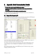
9.2. Automatic and Cyclic Data Transmission
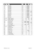
Set any cycle time unequal to zero to parameter F10.110.
Set the serial access code of the register you would like to transmit to parameter F10.111. In
theory you could transmit any of the internal registers by serial link, however only the following
registers make really sense:
F10.111 = 6 : Actual speed of encoder 1
= 7 : Actual speed of encoder 2
= 8 : Actual analogue output voltage (SA models only)
= 9 : Latest minimum value (minimum record memory)
= 10 : Latest maximum value (maximum record memory)
= 14 : Actual value indicated in the display
Dependent on the setting of parameter F10.109 the unit transmits one of the following data
strings, under cycle control of the timer:
(xxxx = counter data*, LF = Line Feed <hex. 0A>, CR = Carriage Return <hex 0D>)
*) Leading zeros will not be transmitted
(Unit No.)
F10.109 = 0 :
1
1
+/-
X
X
X
X
X
X
LF CR
F10.109 = 1 :
+/-
X
X
X
X
X
X
LF CR
9.3. Communication Protocol
When communicating with the unit via protocol, you have full read/write access to all internal
parameters, states and actual counter values. The protocol uses the DRIVECOM standard
according to DIN ISO 1745. A list with the most frequently used serial access codes can be
found in the previous section.
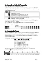
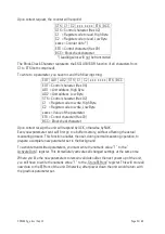
To request data from the counter, the following request string must be sent:
EOT
AD1 AD2 C1 C2 ENQ
EOT = Control character (Hex 04)
AD1 = Unit address, High Byte
AD2 = Unit address, Low Byte
C1 = Register code to read, High Byte
C2 = Register code to read, Low Byte
ENQ = Control character (Hex 05)
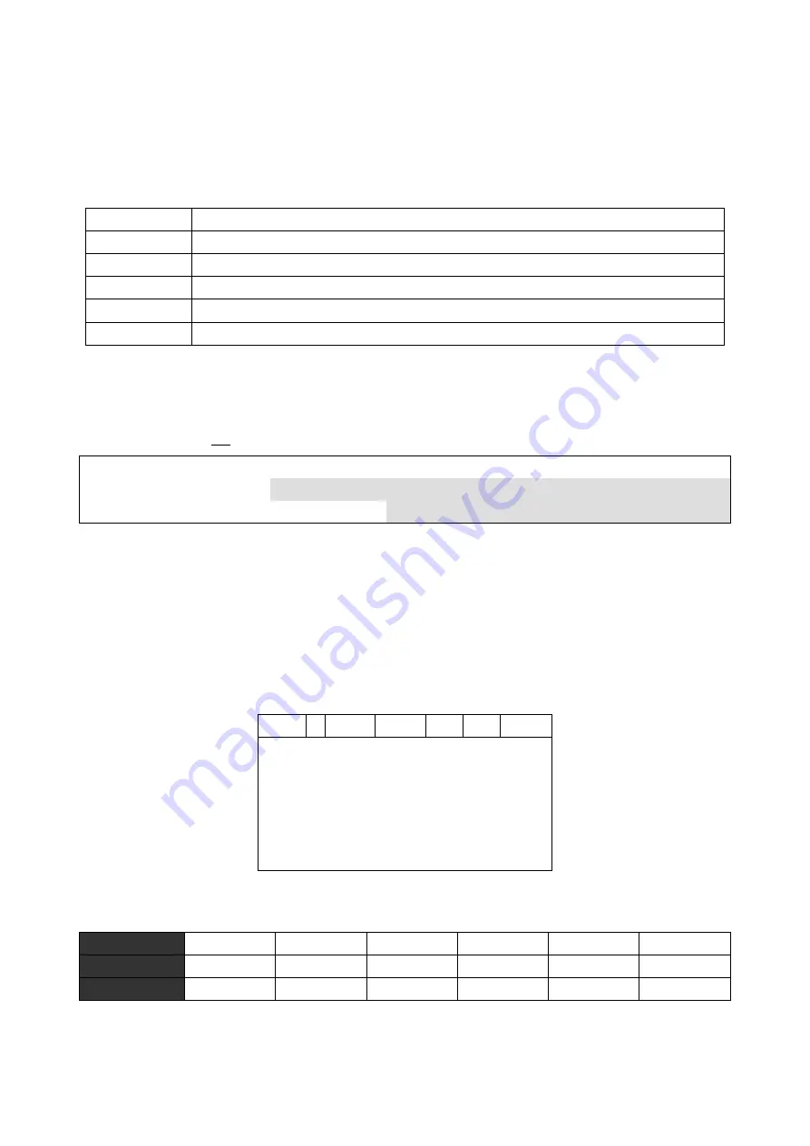
The example shows how to request for transmission of the actual encoder 1 speed
(register code :9), from a unit with unit address 11:
ASCII-Code:
EOT
1
1
:
6
ENQ
Hexadecimal:
04
31
31
3A
39
05
Binary:
0000 0100 0011 0001 0011 0001 0011 1010 0011 1001 0000 0101

