SD34002g_e.doc / Sep-13
Page 45 / 60
7.3. Settings for Example "Differential Speed" of Chapter 4.4
Machine specifications:
Calculations:
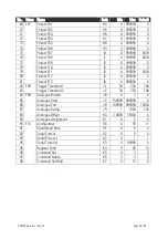
Relevant parameters:
Both encoders:
1024 ppr quadrature
A / B / HTL 24 V
Circumferences (rolls):
all rolls should have the
same circumference of
350 mm
Speeds:
Maximum speed on
both conveyors is
200 m/min
Desired display:
Differential speed with
two decimal positions
(/-99.99 m/min)
Wit a maximum speed of
200 m/min and a roll
circumference of 0.350 m
we will get a roll rpm of
200 m/min : 0,350 m
= 571.43 rpm
This results in encoder
frequencies of
571.43 x 1024 Imp/min
= 585 143 Imp./min
= 9752.4 Imp./sec. (Hz)
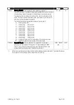
F02.004
3
F02.005
F02.006
F02.007
all = 2
F02.008
F02.009
both = 1000
(no re-scaling necessary)
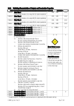
F02.016
1
It is advisable to synchronize
both measuring channels
whenever we use combined
display results
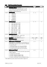
F03.022
F04.034
both = 1
F03.023
F04.035
For correct calculation of the
difference we must ensure that
both speeds have the same
direction (both positive or both
negative), i.e. either
[+Geber1] - [+Geber2] or
[-Geber1] - [-Geber2]
F03.024
F04.036
both = 0.500 (assumed), i.e.
display cycle = 0,5 sec.
F03.025
F04.037
both = 0,20 (assumed), i.e.
speed = 0 with f < 5 Hz
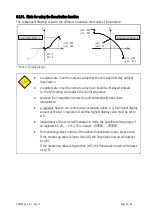
F03.027
F04.039
both = 9752 *)
F03.028
F04.040
both = 20 000 *)
(will appear as 200.00 since we
desire to have two decimal
positions)
F03.029
F04.041
both = 0
*) With high accuracy demand we are free to increase the frequency setting tenfold. This will allow to
also consider the remaining decimal position of our calculation (i.e. F03.027 = 97524).
In order to maintain the proportionality we have then to increase also the desired display value by
factor 10 (i.e. F03.028 = 200 000).

