background image

SD34002g_e.doc / Sep-13

Page 19 / 60

4.7. Percentaged Speed Difference: F02.004 = 7 or 8

Both encoder inputs "encoder1" and "encoder2" are active. With consideration of the individual

scaling of each channel the unit calculates the percentaged difference as shown below:

F02.004 = 7:

Display =

[ sp eed of encoder 1 ]

-

[ speed of encoder 2 ]

[ speed of encoder 2 ]

x 100%

F02.004 = 8:

Display =

[ sp eed of encoder 2 ]

-

[ speed of encoder 1 ]

[ speed of encoder 1 ]

x 100%

Parameter „Percent Format“ (F02.018) determines the number of decimal positions of the result:
0 = display range -999999 to + 9999999 %

1 = display range -99999,9 to +99999,9 %

2 = display range -9999,99 to +9999,99 %

3 = display range -999,999 to +999,999 %

The final percentage result can once more be scaled into user-friendly engineering units by

means of the special scaling parameters in parameter group F02
Besides the actual speeds and the ratio the unit also records minimum and maximum values of
the ratio.
Preset K1 is related to the absolute speed of encoder 1.
Preset K2 is related to the absolute speed of encoder 2.

Presets K3 and K4 are related to the percentaged difference of both speeds

Display

L1 (red)

L2 (yellow)

1 Actual percentage difference

statically ON

statically ON

2 Minimum percentage since last min/max reset

blinking slow

blinking slow

3 Maximum percentage since last min/max reset

blinking fast

blinking fast

4 Actual speed of encoder 1

statically ON

---

5 Actual speed of encoder 2

---

statically ON

Encoder 1

Cont.1

Cont.4

Encoder 2

Remote control functions

f

1

f

2

tension

speed 1

speed 2

speed 2 > speed 1

Example: stretching of material by building up tension

Summary of Contents for SA 330

Page 1: ...terface and analogue output Series SR 4 programmable presets and outputs RS 232 interface and RS485 interface Simultaneous measuring of two independent speeds by means of incremental encoders proximit...

Page 2: ...precautions in order to avoid such consequences Regarding installation wiring environmental conditions screening of cables and earthing you must follow the general standards of industrial automation i...

Page 3: ...20 5 3 Direct Fast Access to Presets 21 5 4 Change of Parameter Values on the Numeric Level 22 5 5 Code Protection against Unauthorized Keypad Access 23 5 6 Return from the Programming Levels and Tim...

Page 4: ...urther properties of the models are fully identical The range of available models also includes units with relay outputs and front thumbwheel switches The following table explains the details of type...

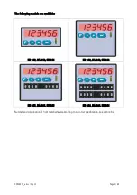
Page 5: ...age 5 60 The following models are available SD 340 SA 340 SR 340 SD 640 SA 640 SR 640 SD 642 SA 642 SR 642 SD 644 SA 644 SR 644 Number and combination of front thumbwheels according to customer specif...

Page 6: ...ed in a reciprocal way i e baking or processing time calculated from the actual speed And still there exist applications where the use of traditional thumbwheel switches offers real advantages compare...

Page 7: ...erface 2 Interface 1 RxD RS232 PROG X1 X2 5 A A B B 5 A A B B Encoder1 Encoder 2 Cont1 Cont2 Cont3 Cont4 Digital Control Inputs RxD TxD GND RS232 24 V DC Power supply Com K1 K4 K1 out K2 out K3 out K4...

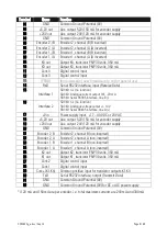
Page 8: ...Serial RS385 interface line B 16 Interface 2 SD 340 n c no function SA 340 Analogue voltage output 10 V SR 340 Serial RS485 interface line A 17 Vin Power supply input 17 40 VDC or 24 VAC 18 5 2V out A...

Page 9: ...TL inputs at a level of 3 0 to 5 volts differential with inverted signal TTL inputs at a level of 3 0 to 5 volts single ended HTL signals at a 10 30 volts level alternatively differential with inverte...

Page 10: ...tor and how to connect the RS485 terminals to a PLC Details about serial communication are shown in chapter 9 2 3 5 RxD RxD TxD TxD GND Screen PC SD 340 SA 340 SR 340 14 Sub D 9 30 31 RS 232 PLC SR 34...

Page 11: ...last reset of the min max memory Scrolling of the display from one reading mode to another will not affect the function of the preselection outputs K1 K4 The analogue output models SA can be assigned...

Page 12: ...of encoder1 speed of encoder2 4 Multiplication mode speed of encoder1 x speed of encoder2 5 Ratio mode speed of encoder1 speed of encoder2 6 Inverse ratio mode speed of encoder2 speed of encoder1 7 Pe...

Page 13: ...ue Display L1 red L2 yellow 1 Actual measuring value of encoder 1 statically ON 2 Minimum value since last min max reset blinking slow 3 Maximum value since last min max reset blinking fast Measuring...

Page 14: ...fer always to the measuring result of encoder 2 Display L1 red L2 yellow 1 Actual measuring value of encoder 1 statically ON 2 Minimum value encoder 1 since last min max reset blinking slow 3 Maximum...

Page 15: ...is related to the absolute speed of encoder 1 Preset K2 is related to the absolute speed of encoder 2 Presets K3 and K4 are related to the actual sum of the speeds encoder 1 encoder 2 Display L1 red...

Page 16: ...eed difference Preset K1 is related to the absolute speed of encoder 1 Preset K2 is related to the absolute speed of encoder 2 Presets K3 and K4 are related to the actual differential speed encoder 1...

Page 17: ...f the product Preset K1 is related to the absolute speed of encoder 1 Preset K2 is related to the absolute speed of encoder 2 Presets K3 and K4 are related to the product of both speeds encoder 1 x en...

Page 18: ...f both speeds Display L1 red L2 yellow 1 Speed ratio encoder 1 or 2 encoder 2 or 1 statically ON statically ON 2 Minimum ratio since last min max reset blinking slow blinking slow 3 Maximum ratio sinc...

Page 19: ...more be scaled into user friendly engineering units by means of the special scaling parameters in parameter group F02 Besides the actual speeds and the ratio the unit also records minimum and maximum...

Page 20: ...ngs defined upon setup All front keys may have customer defined functions according to the specifications met in the keypad definition menu F05 e g scrolling of the display Reset Inhibit etc 5 2 Gener...

Page 21: ...turn to level parameter groups 09 Level Parameter groups Actual value Return to normal operation 10 Normal operation During the general setup procedure all counter activities remain disabled New param...

Page 22: ...o 9 and then shows negative and 1 minus one The example below shows how to change a parameter from the setting 1024 to the new setting 250 000 This example assumes that you have already selected the p...

Page 23: ...d by factory setting For access please use code 6078 5 6 Return from the Programming Levels and Time Out Function At any time the PROG key sets the menu one level up and finally returns to normal oper...

Page 24: ...et those parameters which are really relevant for your specific application Unused parameters can remain like set by default 6 1 Summary of the Menu This section shows a summary of the parameter group...

Page 25: ...input 1 function 016 Synchronization encoder 1 encoder 2 051 Control input 2 characteristics 017 Limitation of input frequency range 052 Control input 2 function 018 Percentaged display format 053 Co...

Page 26: ...tion point y16 replacement F09 Analogue Output Definitions SA only F13 Linearization Table for Encoder 2 100 Output mode voltage current 150 First interpolation point x1 original value 101 Conversion...

Page 27: ...0 5 0 F02 007 Decimal Point 12 position of the decimal point with combinations encoder 1 encoder 2 0 5 0 F02 008 Divider reciprocal scaling factor for combined results 1 999 999 1000 F02 009 Multiplie...

Page 28: ...inputs 2 Limitation to 100 kHz max both encoder inputs 3 Limitation to 10 kHz max both encoder inputs F02 018 Percent Format Decimal presentation of percentaged display 0 3 0 0 Format 999999 1 Format...

Page 29: ...sec 1 00 F03 026 Filter1 Digital filter for smoothing unstable input frequencies for detailed explications see 7 4 0 8 0 0 Filter OFF very fast response to changes in frequency 1 Floating average ove...

Page 30: ...therwise all similar to setting 1 F03 030 Set Value1 Preset value to simulate fixed input frequency 199 999 999 999 x xx Hz 0 When you have assigned the function Set Frequency 1 to any of the front ke...

Page 31: ...delay 001 second 2 timed delay 002 seconds 3 timed delay 004 seconds 4 timed delay 008 seconds 5 timed delay 016 seconds 6 timed delay 032 seconds 7 timed delay 064 seconds 8 timed delay 128 seconds 9...

Page 32: ...zero f 0 0 01 99 99 sec 1 00 F04 038 Filter2 Digital filter for smoothing unstable input frequencies for detailed explications see 7 4 0 8 0 0 Filter OFF very fast response to changes in frequency 1...

Page 33: ...therwise all similar to setting 1 F04 042 Set Value2 Preset value to simulate fixed input frequency 199 999 999 999 x xx Hz 0 When you have assigned the function Set Frequency 2 to any of the front ke...

Page 34: ...delay 001 second 2 timed delay 002 seconds 3 timed delay 004 seconds 4 timed delay 008 seconds 5 timed delay 016 seconds 6 timed delay 032 seconds 7 timed delay 064 seconds 8 timed delay 128 seconds 9...

Page 35: ...tate of output 3 relay 3 d 10 Release maintain latch state of output 4 relay 4 d 11 Release maintain latch state of all outputs relays d 12 Remote start up delay see F03 031 F04 043 s 13 Cycle display...

Page 36: ...utputs relays d 12 Remote start up delay see F03 031 F04 043 s 13 Cycle display d 14 Reset all min max records to the actual display value d 15 Hardware keypad lock s 16 Read thumbwheel switches d b 1...

Page 37: ...tual Value Preset No start up delay Maintain latch is possible 1 Switches with Actual Value Preset Includes start up delay Maintain latch is possible 2 Window characteristics Switches ON with Actual V...

Page 38: ...K3 binary value 4 K4 binary value 8 Bit 0 no start up delay Bit 1 start up delay active F06 075 Lock Configuration 0 15 without Auto Release or 16 31 with Auto Release 0 Assignment of maintain latch...

Page 39: ...and F11 Linearization are already protected by factory setting For access please use code 6078 6 2 7 Special Functions F08 Range Default F08 095 Trigger Threshold 1 30 250 166 Switching threshold for...

Page 40: ...9 Serial Printer Protocol 0 1 1 0 Output string Unit Nr Data LF CR 1 Output string Data LF CR F10 110 Serial Timer for timed transmissions sec 0 000 99 999 0 000 F10 111 Serial Parameter code 0 26 14...

Page 41: ...117 Mode of linearization for speed 2 encoder 2 0 Linearisation off 1 Linearisation is defined for the numeric range from 0 to 999 999 only and negative values will appear as a mirror of the positive...

Page 42: ...ead i e the y3 setting will replace the x3 display value between the interpolation points the unit automatically uses linear interpolation x registers have to use continuously increasing values e g th...

Page 43: ...9 999 3000 3 F01 Preselection 4 03 19 999 999 99 999 999 4000 11 F02 Offset A7 19 999 999 99 999 999 0 27 F03 Set Value 1 C6 19 999 999 99 999 999 0 37 F04 Set Value 2 D8 19 999 999 99 999 999 0 85 F0...

Page 44: ...er frequency is 40 960 Hz We expect a display value of 3000 to display 300 0 F02 004 0 F02 0005 1 F03 022 0 F03 024 0 100 assumed i e display cycle 0 1 sec F03 025 0 10 display zero with f 10 Hz F03 0...

Page 45: ...necessary F02 016 1 It is advisable to synchronize both measuring channels whenever we use combined display results F03 022 F04 034 both 1 F03 023 F04 035 For correct calculation of the difference we...

Page 46: ...switched off b With Filter set to 1 the unit forms a floating average value over the last two measuring cycles As a result after the first sampling period we can only see 50 of the jump and only one...

Page 47: ...open Normally closed 8 2 Front Thumbwheel Switches Moreover the models shown below provide thumbwheel switches on the front panel for simple and easy setting of preselection levels Every row allows i...

Page 48: ...ation 8 3 2 Positive or negative sign of thumbwheel settings In general and as a default the front thumbwheel settings are assumed to have a positive sign Some applications may however require that on...

Page 49: ...2 03 04 05 06 07 08 09 10 11 Thumbwheel set 1 is linked to output K1 K1 K1 K1 K1 K1 K2 K2 K2 K2 K2 K2 Thumbwheel set 2 is linked to output K2 K2 K3 K3 K4 K4 K1 K1 K3 K3 K4 K4 Thumbwheel set 3 is linke...

Page 50: ...ecial SERPRO manual 9 1 Setup of the Counter by PC Connect the counter to your PC as shown in section 3 6 of this manual Start the OS32 Operator software After a short initializing time you will see t...

Page 51: ...ge Return hex 0D Leading zeros will not be transmitted Unit No F10 109 0 1 1 X X X X X X LF CR F10 109 1 X X X X X X LF CR 9 3 Communication Protocol When communicating with the unit via protocol you...

Page 52: ...te C2 Register code to write Low Byte xxxxx Value of the parameter ETX Control character Hex 03 BCC Block check character Upon correct receipt the unit will respond by ACK otherwise by NAK Every new p...

Page 53: ...05 050 14 61 Cycle the display see F05 050 13 62 Remote start up delay see F05 050 12 63 Release latch maintain of outputs and relays see F10 114 64 Freeze encoder frequencies see F10 113 65 Substitut...

Page 54: ...lay Value A5 1 999999 1000 10 Display Mode A6 0 3 0 11 Offset A7 199999 999999 0 12 Brightness A8 0 4 0 13 Display Update A9 0 100 0 14 Sampling Pulses B0 0 30000 0 15 Wait Time Sampling B1 0 9999 50...

Page 55: ...1 Function E6 0 17 0 45 Input 2 Configuration E7 0 7 0 46 Input 2 Function E8 0 17 0 47 Input 3 Configuration E9 0 7 0 48 Input 3 Function F0 0 17 0 49 Input 4 Configuration F1 0 3 0 50 Input 4 Functi...

Page 56: ...80 Protect F12 I5 0 999999 0 81 Protect F13 I6 0 999999 0 82 F08 Trigger Threshold 1 J1 30 250 166 83 Trigger Threshold 2 J2 30 250 166 84 F09 Analogue Format J6 0 3 0 85 Analogue Start J7 199999 999...

Page 57: ...Max 61 0040 4 Display Switch 62 0020 5 Startup Inhibit 63 0010 6 Selfhold Release 64 0008 7 Freeze Frequency 65 0004 8 Set Frequency 66 0002 9 Activate Data 67 1000 10 Store EEProm 68 0001 No Name Cm...

Page 58: ...y max 100 V 1A 100 W Serial link SD SA RS232 2400 38400 Bauds SR RS232 and RS485 2400 38400 Bauds Analogue outputs models SA only 0 4 20mA load max 270 Ohm 0 10V load max 2 mA Resolution 14 bits Accur...

Page 59: ...D34002g_e doc Sep 13 Page 59 60 11 Dimensions Models 340 96 0 3 780 110 0 4 331 44 0 1 732 10 0 394 8 0 315 91 0 3 583 9 0 345 129 0 5 079 140 5 5 531 48 0 1 890 Panel cut out 91 x 44 mm 3 583 x 1 732...

Page 60: ...3 780 110 0 4 331 90 5 3 563 10 0 394 8 0 315 88 5 3 484 9 0 345 129 0 5 079 140 5 5 531 96 0 3 78 18 5 728 111 5 4 39 With optional plexi glass cover for protection class IP65 mks part 64026 12 0 472...

Reviews: