


Loading Application Software
Firmware
4 - 12
PPC/PMC-8260/DS1
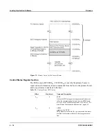
System State at ROM Image Execution
For an application it is important to know how the CPU and peripherals are config-
ured when control is passed to the ROM image.
CPU Registers
The following CPU registers are initialized during cold boot:
•
Machine State register (MSR) is set to 0
•
SPRG registers are set to 0
•
Segment registers are set to 0
•
All D and IBAT registers are cleared.
•
The translation lookaside buffers (TLBs) are invalidated
Caches
Both the instruction and the data cache are disabled. The contents of the caches are
not explicitely cleared by the firmware. If shadowing a ROM image to RAM for
execution, the instruction cache will be enabled.
MMU
The Memory Management Unit (MMU) and block address translation mechanism
is not used by the firmware.
Memory Controller
The memory controller is programmed according to table 21 “Memory Map” on
page 5-3.
PowerSpan II
The firmware uses mailbox registers 5, 6 and 7 as control and status registers. Fur-
thermore, it programs the address translation of PCI base address register 2 so that
it is mapped to the local DRAM.
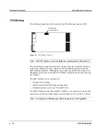
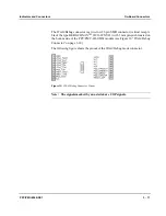
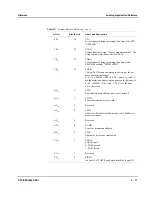
Port Pin Configuration
The firmware does not program the pin assignment registers for ports A-C. If you
have purchased the Motorola Tornado 2.0 BSP for the PPC/PMC-8260/DS1 or one
of the Motorola stackware packages, you do not need to program the PowerQUICC
II port pins. If not, the “PowerQUICC II Port Functions on PMC-8260/DS1” sec-
tion page 6-11 gives information which port functions must be programmed.
Dual-Ported RAM
Parts of the dual-ported RAM are used by the power-on self test:
•
The first 268 bytes are overwritten by the memory test.
•
The address range from B800
16
to B82F
16
is used to store the POST results.
Other
PowerQUICC II
Settings
The firmware does not change any settings in the PowerQUICC II register set
except the registers for the memory controller and the SYPCR register, if
SYPCR_VAL and SYPCR_WR are programmed in the ROM image configuration
section.
Summary of Contents for PPC/PMC-8260/DS1
Page 1: ...PPC PMC 8260 DS1 Reference Guide P N 6806800B10A July 2006 ...
Page 8: ...viii PPC PMC 8260 DS1 ...
Page 22: ...xxii PPC PMC 8260 DS1 ...
Page 26: ...xxvi PPC PMC 8260 DS1 ...
Page 30: ...xxx PPC PMC 8260 DS1 ...
Page 31: ...1 Introduction ...
Page 32: ......
Page 39: ...2 Installation ...
Page 40: ......
Page 53: ...3 Indicators and Connectors ...
Page 54: ......
Page 64: ...On Board Connectors Indicators and Connectors 3 12 PPC PMC 8260 DS1 ...
Page 65: ...4 Firmware ...
Page 66: ......
Page 104: ...Code Examples Firmware 4 40 PPC PMC 8260 DS1 ...
Page 105: ...5 Memory Map and Devices ...
Page 106: ......
Page 132: ...Resetting the Devices Memory Map and Devices 5 28 PPC PMC 8260 DS1 ...
Page 133: ...6 TDM Channel Configuration ...
Page 134: ......
Page 145: ...A Troubleshooting ...
Page 146: ......
Page 148: ...A 4 PPC PMC 8260 DS1 ...
Page 150: ...I 2 PPC PMC 8260 DS1 ...