


Motorola PowerQUICC II
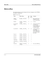
Memory Map and Devices
5 - 6
PPC/PMC-8260/DS1
Motorola PowerQUICC II
The PowerQUICC II (MPC8260 HiP4) is a versatile microprocessor and peripheral
controller for communication and networking applications. It has a core frequency
of 300 MHz and a Communication Processor Module (CPM) frequency of 200
MHz. If you need additional information to the information given in this section,
refer to the
MPC8260 PowerQUICC II User’s Manual
and the
MPC8260 Power-
QUICC II User’s Manual MPC8260A (HiP4) Supplement
.
Bus Monitor
The PowerQUICC II has two bus monitors, one for the 60x bus and one for the lo-
cal bus. They monitor the accesses to the memory and the I/O devices and generate
a machine check or reset interrupt if the time-out value is reached.
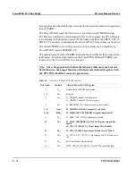
By default, the bus monitor on the PPC/PMC-8260/DS1 is active upon booting and
the time-out value is set to 30.9
μ
sec. If you want to disable the bus monitor be-
cause the short time-out value could create an undesired machine check or reset in-
terrupt, this can be programmed into the ROM image. The firmware then sets the
SYPCR register accordingly. For further information, refer to the “ROM Image
Configuration” section on page 4-9.
Communication Processor Module
The CPM contains features that allow the PowerQUICC II to excel in a variety of
applications targeted mainly for networking and telecommunication markets.
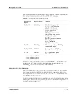
Serial Communication Channels
The PowerQUICC II has six channels for serial communication: two SMCs (Serial
Management Controller) called SMC_1 and SMC_2 and four SCCs (Serial Com-
munication Controller) called SCC_1…SCC_4. They are connected to the
PPC/PMC-8260/DS1 interfaces as follows:
•
SCC_1 is connected to the 9-pin MicroD-Sub connector on the front panel via
an RS-232 driver.
•
SMC_1 is connected to the debug mode connector via RS-232 drivers.
•
SCC_2 is used in a factory option for 10BaseT Ethernet on the front panel 9-pin
MicroD-Sub (external PHY is needed).
•
SCC_3 is used as CT-Bus Management Bus (CT_MC).
•
SMC_2 and SCC_4 are not connected to any external devices.
Summary of Contents for PPC/PMC-8260/DS1
Page 1: ...PPC PMC 8260 DS1 Reference Guide P N 6806800B10A July 2006 ...
Page 8: ...viii PPC PMC 8260 DS1 ...
Page 22: ...xxii PPC PMC 8260 DS1 ...
Page 26: ...xxvi PPC PMC 8260 DS1 ...
Page 30: ...xxx PPC PMC 8260 DS1 ...
Page 31: ...1 Introduction ...
Page 32: ......
Page 39: ...2 Installation ...
Page 40: ......
Page 53: ...3 Indicators and Connectors ...
Page 54: ......
Page 64: ...On Board Connectors Indicators and Connectors 3 12 PPC PMC 8260 DS1 ...
Page 65: ...4 Firmware ...
Page 66: ......
Page 104: ...Code Examples Firmware 4 40 PPC PMC 8260 DS1 ...
Page 105: ...5 Memory Map and Devices ...
Page 106: ......
Page 132: ...Resetting the Devices Memory Map and Devices 5 28 PPC PMC 8260 DS1 ...
Page 133: ...6 TDM Channel Configuration ...
Page 134: ......
Page 145: ...A Troubleshooting ...
Page 146: ......
Page 148: ...A 4 PPC PMC 8260 DS1 ...
Page 150: ...I 2 PPC PMC 8260 DS1 ...