


1-8
Computer Group Literature Center Web Site
Hardware Preparation and Installation
1
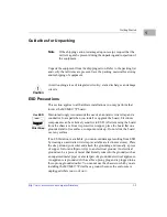
!
Caution
Removing all jumpers may temporarily disable the SRAM. Do not remove
all jumpers from J9, except for storage.
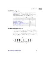
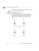
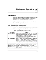
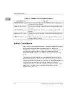
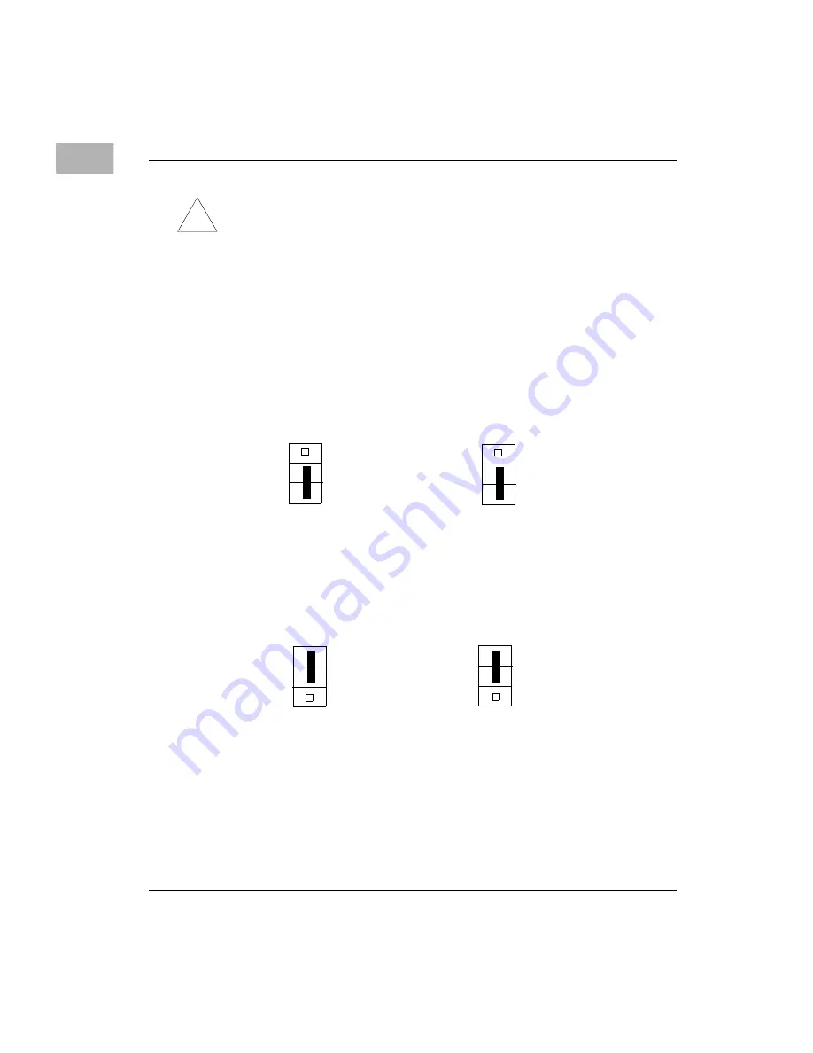
Serial Port 4 Clock Configuration (J10 and J11)
Serial port 4 can be configured to use clock signals provided by the
RTXC4 and TRXC4 signal lines. Headers J10 and J11 on the MVME177P
configure serial port 4 to drive or receive TRXC4 and RTXC4,
respectively. The factory configuration has port 4 set to receive both
signals.
Receive TRXC4
J11
1
3
J10
1
3
Receive RTXC4
(Factory Configurations)
Drive TRXC4
J11
1
3
J10
Drive RTXC4
1
3
Summary of Contents for MVME177P
Page 1: ...MVME177P Single Board Computer Installation and Use V177PA IH1 Edition of October 2000 ...
Page 10: ...x ...
Page 12: ...xii ...
Page 14: ...xiv ...
Page 34: ...1 16 Computer Group Literature Center Web Site Hardware Preparation and Installation 1 ...
Page 48: ...2 14 Computer Group Literature Center Web Site Startup and Operation 2 ...
Page 92: ...C 2 Computer Group Literature Center Web Site Network Controller Data C ...
Page 98: ...D 6 Computer Group Literature Center Web Site Disk Tape Controller Data D ...
Page 108: ...Index IN 6 Computer Group Literature Center Web Site I N D E X ...


