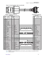
Number
Description
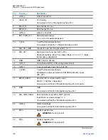
4
GPS Antenna SMA Connector
6.1.4
Completing Radio Installation
Procedure:
1
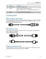
Mount the microphone clip to a convenient spot near your radio.
2
If your microphone has a telephone-type connector at the end of its cord, plug this connector
into the 10-pin TELCO connector of your Junction Box.
CAUTION:
DO NOT use the 10-pin TELCO connector of Data Expansion Head Enhanced or Remote Head
Enhanced to plug in a microphone.
3
Plug the power cable into the radio power connector.
NOTICE:
Motorola Solutions supplies a wide range of antennas and associated coaxial cables
correctly terminated for use with the mobile radio. However should the need arise to
carry out reinstallation or repair of a cable or connector then suitable information on
selection and installation of replacement connectors and cables can be found on most
recognized connector and cable manufacturers, for example Radiall, Huber and Suhner,
Samtec.
The BNC Connector should be typically of the crimped variety, likewise the SMA, or FME
Connector used for GPS should also be of the crimped variety. Coaxial cable should be
screened and low loss, see the individual specification sheets for the antennas to find
details of specific cable types and or connectors. Additionally see the TETRA Interface
Specification for the mobile radios for further information.
6.2
Installing External Speaker
Procedure:
1
Remove the speaker from the trunnion bracket by loosening the two wing screws.
2
Choose a place to mount the speaker. When mounting the trunnion on the transmission hump,
be careful that the transmission housing is not affected.
3
Use the trunnion bracket as a template to mark the positions of the mounting holes.
4
Centre-punch the spots you marked and drill a 4 mm (5/32-inch) diameter hole at each location.
68015000553-KC
Chapter 6: External Equipment Installation
119
Summary of Contents for MTM800 FuG ET
Page 2: ......
Page 4: ...This page intentionally left blank ...
Page 8: ...This page intentionally left blank ...
Page 12: ...This page intentionally left blank ...
Page 15: ...Table 73 Fuse Identification 131 68015000553 KC List of Tables Send Feedback 15 ...
Page 16: ...This page intentionally left blank ...
Page 18: ...This page intentionally left blank ...
Page 34: ...This page intentionally left blank ...
Page 126: ...This page intentionally left blank ...
Page 130: ...This page intentionally left blank ...
Page 132: ...This page intentionally left blank ...
Page 134: ...This page intentionally left blank ...
Page 138: ...Diese Seite wurde absichtlich leer gelassen ...
Page 142: ...Diese Seite wurde absichtlich leer gelassen ...
Page 146: ...Diese Seite wurde absichtlich leer gelassen ...
Page 148: ...Diese Seite wurde absichtlich leer gelassen ...
Page 220: ...Diese Seite wurde absichtlich leer gelassen ...
Page 250: ...Diese Seite wurde absichtlich leer gelassen ...
Page 260: ...Diese Seite wurde absichtlich leer gelassen ...
Page 264: ...Diese Seite wurde absichtlich leer gelassen ...
Page 266: ...Diese Seite wurde absichtlich leer gelassen ...


