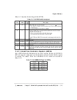
Chapter 11. Embedded Programmable Interrupt Controller (EPIC) Unit
11-9
EPIC Unit Interrupt Protocol
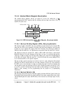
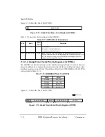
11.3.6 Internal Block Diagram Description
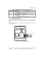
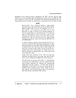
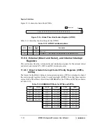
The internal block diagram shown in Figure
11-2 shows the interaction of the
non-programmable EPIC registers and the interrupt delivery logic (assertion of the int
signal to the processor).
Figure 11-2. EPIC Interrupt Generation Block Diagram—Non-programmable
Registers
11.3.6.1 Interrupt Pending Register (IPR)—Non-programmable
The interrupt signals in the EPIC unit are qualified and synchronized by the internal IPR,
which has one bit for each interrupt. The mask bits from the appropriate vector/priority
register are used to qualify the output of the IPR. Therefore, if an interrupt condition is
detected when the mask bit is set, that interrupt is requested when the mask bit is cleared.
The interrupt sources are internal (I
2
C, DMA or MU); EPIC (four timers); and external
IRQ[0:4] (direct) or 16 serial interrupts. When there is a direct or serial interrupt and the
sense bit = 0 (edge-sensitive), the interrupt acknowledge cycle causes the corresponding bit
in the IPR to be cleared. When the sense bit = 1 (level-activated), the corresponding IPR bit
is not cleared until the source signal is negated.
Because an edge-sensitive interrupt is not cleared until it is acknowledged and the default
polarity/sense bits for all interrupts are set to edge-sensitive at power-up, it is possible for
the EPIC unit to store detections of edges as pending interrupts. If software permanently
sets the polarity/sense of an interrupt source to edge-sensitive and clears its mask bit, it can
receive the vector for the interrupt source and not a spurious interrupt. To prevent having to
handle a false interrupt, see the programming note in Section 11.8, “Programming
Guidelines.”
11.3.6.2 Interrupt Selector (IS)
The interrupt selector (IS) receives interrupt requests from the IPR. The output of the IS is
the highest priority interrupt that has been qualified. This output contains the priority of the
selected interrupt and its source identification. The IS resolves an interrupt request in two
clocks.
Interrupt sources:
Interrupt pending register
Interrupt selector
In-Service register
Interrupt request register
2 clocks
EOI cycle (1 clock)
direct
serial
internal timers
IACK/EOI
EOI
int
Summary of Contents for MPC8240
Page 1: ...MPC8240UM D Rev 1 1 2001 MPC8240 Integrated Processor User s Manual ...
Page 38: ...xviii MPC8240 Integrated Processor User s Manual TABLES Table Number Title Page Number ...
Page 48: ...xlviii MPC8240 Integrated Processor User s Manual Acronyms and Abbreviations ...
Page 312: ...6 94 MPC8240 Integrated Processor User s Manual ROM Flash Interface Operation ...
Page 348: ...7 36 MPC8240 Integrated Processor User s Manual PCI Host and Agent Modes ...
Page 372: ...8 24 MPC8240 Integrated Processor User s Manual DMA Register Descriptions ...
Page 394: ...9 22 MPC8240 Integrated Processor User s Manual I2O Interface ...
Page 412: ...10 18 MPC8240 Integrated Processor User s Manual Programming Guidelines ...
Page 454: ...12 14 MPC8240 Integrated Processor User s Manual Internal Arbitration ...
Page 466: ...13 12 MPC8240 Integrated Processor User s Manual Exception Latencies ...
Page 516: ...16 14 Watchpoint Trigger Applications ...
Page 538: ...B 16 MPC8240 Integrated Processor User s Manual Setting the Endian Mode of Operation ...
Page 546: ...C 8 MPC8240 Integrated Processor User s Manual ...
Page 640: ...INDEX Index 16 MPC8240 Integrated Processor User s Manual ...


