


8-12
MPC8240 Integrated Processor User’s Manual
DMA Descriptors for Chaining Mode
8.5.3.4 Attempted Access to ROM on the PCI Bus—Agent Mode
If the CDAR[CTT] indicates that the transferred address is for ROM on the PCI bus and the
ROM is located locally, then the transaction is issued to the PCI bus and results in a master
abort (and DSR[PE] is set) or a completed transaction, depending on whether a device is
configured on the PCI bus in that address space.
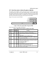
8.6 DMA Descriptors for Chaining Mode
For DMA chaining mode, DMA descriptors are constructed in either local or PCI memory
and linked together by the next descriptor field. The descriptor contains information for the
DMA controller to transfer data. Software must ensure that each segment descriptor is
aligned on an 8-word boundary. The last descriptor in memory must have the EOTD bit set
in the next descriptor field, indicating that this is the last descriptor in memory.
Software initializes the CDAR to point to the first descriptor in memory. The DMA
controller traverses through the descriptor chain until the last descriptor is read. For each
descriptor in the chain, the DMA controller starts a new DMA transfer with the control
parameters specified by the descriptor.
Table 8-2 summarizes the fields of DMA descriptors.
Table 8-2. DMA Descriptor Summary
Descriptor Field
Description
Source address
Contains the source address of the DMA transfer. When the DMA controller reads the
descriptor from memory, this field is loaded into the SAR as described in Table 8-4.
Destination address
Contains the destination address of the DMA transfer. When the DMA controller reads the
descriptor from memory, this field is loaded into the DAR as described in Table 8-4.
Next descriptor
address
Points to the next descriptor in memory. When the DMA controller reads the descriptor
from memory, this field is loaded into the NDAR as described in Table 8-4. If the current
descriptor is the last descriptor in memory, then the EOTD bit in this descriptor field must
be set.
Byte count
Contains the number of bytes to transfer. When the DMA controller reads the descriptor
from memory, this field is loaded into the BCR as described in Table 8-8.
Summary of Contents for MPC8240
Page 1: ...MPC8240UM D Rev 1 1 2001 MPC8240 Integrated Processor User s Manual ...
Page 38: ...xviii MPC8240 Integrated Processor User s Manual TABLES Table Number Title Page Number ...
Page 48: ...xlviii MPC8240 Integrated Processor User s Manual Acronyms and Abbreviations ...
Page 312: ...6 94 MPC8240 Integrated Processor User s Manual ROM Flash Interface Operation ...
Page 348: ...7 36 MPC8240 Integrated Processor User s Manual PCI Host and Agent Modes ...
Page 372: ...8 24 MPC8240 Integrated Processor User s Manual DMA Register Descriptions ...
Page 394: ...9 22 MPC8240 Integrated Processor User s Manual I2O Interface ...
Page 412: ...10 18 MPC8240 Integrated Processor User s Manual Programming Guidelines ...
Page 454: ...12 14 MPC8240 Integrated Processor User s Manual Internal Arbitration ...
Page 466: ...13 12 MPC8240 Integrated Processor User s Manual Exception Latencies ...
Page 516: ...16 14 Watchpoint Trigger Applications ...
Page 538: ...B 16 MPC8240 Integrated Processor User s Manual Setting the Endian Mode of Operation ...
Page 546: ...C 8 MPC8240 Integrated Processor User s Manual ...
Page 640: ...INDEX Index 16 MPC8240 Integrated Processor User s Manual ...