4-42
MPC8240 Integrated Processor User’s Manual
Memory Control Configuration Registers
4.10 Memory Control Configuration Registers
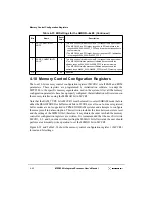
The four 32-bit memory control configuration registers (MCCRs) set all RAM and ROM
parameters. These registers are programmed by initialization software to adapt the
MPC8240 to the specific memory organization used in the system. After all the memory
configuration parameters have been properly configured, the initialization software turns on
the memory interface using the MEMGO bit in MCCR1.
Note that the RAM_TYPE bit in MCCR1 must be cleared (to select SDRAM mode) before
either the REGISTERED or buffer mode bits in MCCR4 are set to one. In-line or registered
buffer modes are not supported in FPM/EDO DRAM systems and attempts to configure
them may result in data corruption. This restriction includes the time between system reset
and the setting of the MEMGO bit; therefore, it may dictate the order in which the memory
controller configuration registers are written. It is recommended that the user first write
MCCR1, 2, 3, and 4, in order, without setting the MEMGO bit. Afterwards, the user should
perform a read-modify-write operation to set the MEMGO bit in MCCR1.
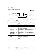
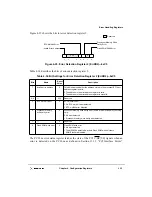
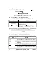
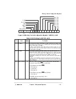
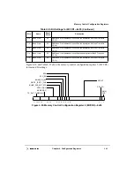
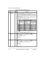
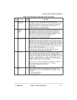
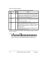
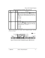
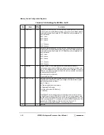
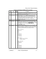
Figure 4-29 and Table 4-38 show the memory control configuration register 1 (MCCR1)
format and bit settings.
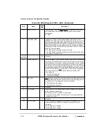
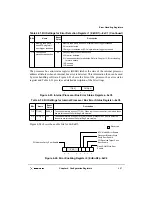
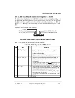
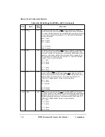
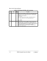
3
PCI_COMPATIBILITY_
HOLE
0
This bit is used only for address map B (not supported in agent mode).
0 The MPC8240, as a PCI target, responds to PCI addresses in the
range 0x000A_0000–0x000F_FFFF and forwards the transaction to
system memory.
1 The MPC8240, as a PCI target, does not respond to PCI addresses
in the range 0x000A_0000–0x000F_FFFF.
2
PROC_COMPATIBILITY_
HOLE
0
This bit is used only for address map B (not supported in agent mode).
0 The MPC8240 forwards processor-initiated transactions in the
address range 0x000A_0000–0x000B_FFFF to system memory.
1 The MPC8240 forwards processor-initiated transactions in the
address range 0x000A_0000–0x000B_FFFF to the PCI memory space.
1–0
—
00
Reserved
Table 4-37. Bit Settings for the AMBOR—0xE0 (Continued)
Bits
Name
Reset
Value
Description
Summary of Contents for MPC8240
Page 1: ...MPC8240UM D Rev 1 1 2001 MPC8240 Integrated Processor User s Manual ...
Page 38: ...xviii MPC8240 Integrated Processor User s Manual TABLES Table Number Title Page Number ...
Page 48: ...xlviii MPC8240 Integrated Processor User s Manual Acronyms and Abbreviations ...
Page 312: ...6 94 MPC8240 Integrated Processor User s Manual ROM Flash Interface Operation ...
Page 348: ...7 36 MPC8240 Integrated Processor User s Manual PCI Host and Agent Modes ...
Page 372: ...8 24 MPC8240 Integrated Processor User s Manual DMA Register Descriptions ...
Page 394: ...9 22 MPC8240 Integrated Processor User s Manual I2O Interface ...
Page 412: ...10 18 MPC8240 Integrated Processor User s Manual Programming Guidelines ...
Page 454: ...12 14 MPC8240 Integrated Processor User s Manual Internal Arbitration ...
Page 466: ...13 12 MPC8240 Integrated Processor User s Manual Exception Latencies ...
Page 516: ...16 14 Watchpoint Trigger Applications ...
Page 538: ...B 16 MPC8240 Integrated Processor User s Manual Setting the Endian Mode of Operation ...
Page 546: ...C 8 MPC8240 Integrated Processor User s Manual ...
Page 640: ...INDEX Index 16 MPC8240 Integrated Processor User s Manual ...


