KITEVS2107QS/D
MOTOROLA
Quick Start Guide
1
Quick Start Guide — KITEVSMMC2107
Evaluation System
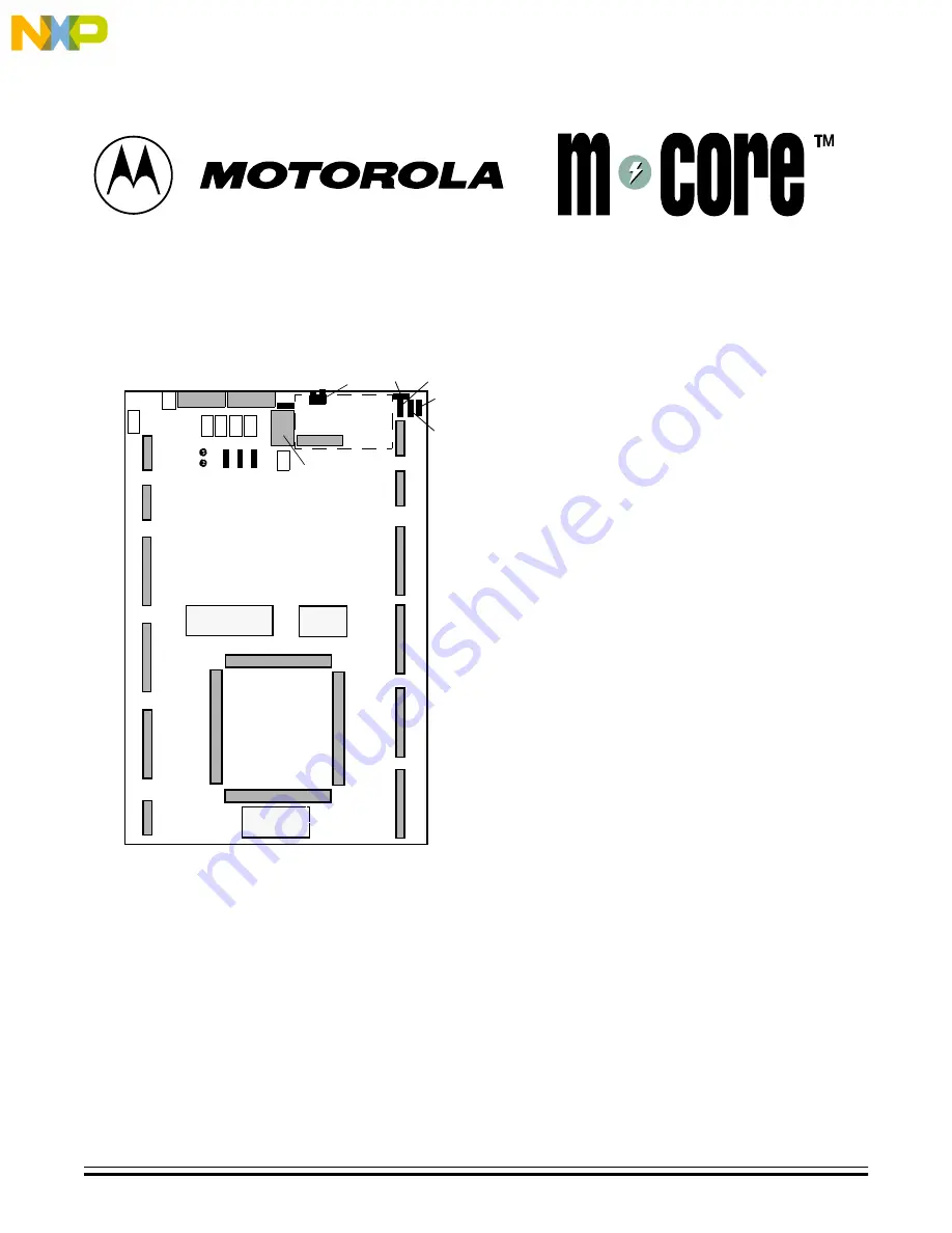
MMCMPFB1200 Platform Board
Install GNU Tools
1.
Insert the CD-ROM into your CD-ROM drive.
The install shield should begin automatically.
(If the install shield does not start automatically,
click on the Start button and select Run. Then
use the Run dialog box to run file
Autorun.exe
of the CD-ROM.)
2.
An M
•
CORE install screen appears. Click on the
M
•
CORE Tools button to bring up a second
screen.
3.
Click on the Install GNU Tools button, then
follow the instructions of successive screens to
install the tools into the default directory.
An installation-complete message indicates
successful installation.
4.
Click on the OK button of the message box to
return to the second screen, then click on the
Exit button.
NOTE: If the GNU tools do not work after
installation your initial environment space may
be too small: it should be at least 4096 bytes.
(The way to make this setting may be different
for each system. For assistance, refer to your
Windows documentation, to Microsoft technical
support, or to Motorola technical support.)
Connect Your Boards
1.
Make sure that all switches and jumper headers
of your MPFB1200 and CMB2107 have the
factory configuration.
2.
Place the MPFB1200 on your work surface.
Hold the CMB2107 directly above the
MPFB1200. Orient the CMB2107 to align the
silk-screen right-triangle markings, at the ends
of the boards’ MAPI connectors P1 and P2.
3.
Press the boards together, so that CMB2107
MAPI connectors J1 through J4 (on the bottom
of the board) connect with corresponding
MPFB1200 MAPI connectors P1 through P4.
Connect Boards to Your System
1.
Connect the RS-232 cable between CMB2107
connector J58 and the serial port of your
computer. (If appropriate, use the DB9/DB25
adapter.)
2.
Connect the +12-volt power supply to
MPFB1200 connector J17. (Do not connect a
power supply directly to the CMB2107: the
platform board supplies CMB power through the
MAPI ring.)
P4
P3
P1
P2
P3
J6
J7
J16
J8
J10
J12
J14
J5
J9
J11
J13
J15
Breadboard Areas
Breadboard
Area
W10
F1
J17
J18
J29
DS1
W1 W2 W3 W4
J19
J20
W9
W8
W7
DS2
DS3
J21
LCD display location
W5
J24
W6
U1
June 2000
F
re
e
sc
a
le
S
e
m
ic
o
n
d
u
c
to
r,
I
Freescale Semiconductor, Inc.
For More Information On This Product,
Go to: www.freescale.com
n
c
.
..


