background image

Operation

Digital Remote Control Radio Operation

3-14

MC3000 Digital Deskset Operator and Installation Manual

(6880309L15-A)

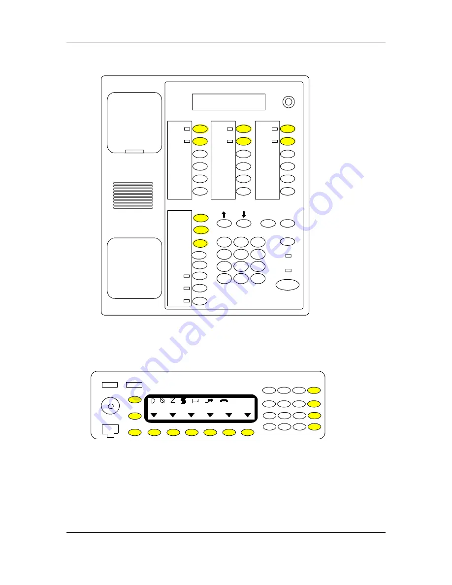
Figure 3-7: MC3000 to MCS 2000 (model III)

D

E

I

F

H

1

2

3

4

5

6

7

7

8

9

*

0

#

G

Sel

Menu /

Home

MCS

Intercom

Speaker

Takeover

Tx

Busy

/\

N/A

N/A

C

B

A

A

B

C

D

E

F

G

I

H

1

2

3

4

5

6

DWN

7

8

9

SEL

*

0

#

MENU

UP

The function buttons are shaded.

Summary of Contents for MC3000

Page 1: ...MC3000 Digital Deskset L3223 Operator and Installation Manual 6880309L15 A 21 June 2002 ...

Page 2: ...EVENT SHALL MOTOROLA BE LIABLE FOR INCIDENTAL OR CON SEQUENTIAL DAMAGES TO THE FULL EXTENT SUCH MAY BE DISCLAIMED BY LAW In the event of a defect malfunction or failure to conform to specifications established by seller or if appropriate to specifications accepted by Seller in writing during the period shown Motorola at its option will either repair or replace the product or refund the purchase pr...

Page 3: ... Related Information 1 7 Chapter 2 Installation 2 1 Introduction 2 1 Preparing for Installation 2 2 Equipment 2 2 Documentation and Software 2 2 Safety Considerations 2 2 Using Digital Junction Box to Connect a Single Deskset 2 3 Using Digital Junction Box to Connect Multiple Desksets 2 4 Opening Deskset 2 6 Connecting Deskset to Alarms 2 7 Setting Jumpers 2 7 Setting DIP Switches 2 8 Back Panel C...

Page 4: ...eskset Overview 3 2 Communication Options 3 4 Handset Operation 3 4 Using the Handset PTT Button 3 4 Enabling the Internal Speaker 3 4 Internal Speaker and Microphone Operation 3 5 Optional Desk Microphone or Headset Footswitch Operation 3 5 Headset 3 6 Microphones 3 6 Takeover Button Operation 3 7 LCD Display 3 7 Keypad Operation 3 8 Monitoring the Radio Channel 3 9 Dial Up Connection to the Radi...

Page 5: ...n Manual iii 6880309L15 A Appendix A The Labels Program A 1 About the Labels Program A 1 Starting the Labels Program A 1 Help Feature A 2 Toolbar A 2 Creating a New Label File A 3 Adding and or Editing Label Text A 5 Producing Labels A 9 Glossary Glossary 1 ...

Page 6: ...Contents iv MC3000 Digital Deskset Operator and Installation Manual 6880309L15 A ...

Page 7: ...u connect the deskset to a different digital radio type MC3000 Deskset Overview The MC3000 Digital Deskset is a small footprint radio dispatch console designed to satisfy the needs of digital radio users who require multiple dispatch points with enhanced talk listen and inter dispatcher intercom The MC3000 is the approximate size and shape of an office telephone set with a tele phone like handset ...

Page 8: ...Up to thirty one MC3000 Desksets can operate in parallel without degradation in perfor mance A Digital Junction Box L3208 is required to connect one or more desksets to a radio or L3239 for LTR radio The maximum aggregate cable length between desksets and the master Digital Junction Box is 5000 ft The MC3000 Deskset operates on 12 VDC using an external in line 120 240 VAC 50 60 Hz power supply ...

Page 9: ...tal Deskset Operator and Installation Manual 1 3 6880309L15 A Model Information Figure 1 1 MC3000 Digital Deskset 1 A 2 abc 3 def 4 ghi 5 jkl 6 mno 7 prs 8 tuv 9 wxy 0 qz B C D Takeover Intercom Speaker Volume Sel Menu Home TWO LINE x 20 MC3000 Busy Transmit ...

Page 10: ...C Humidity 95 at 122 F 50 C non condensing Power Input 10 5 16 VDC maximum Frequency Response 3dB from 300 3000 Hz 1kHz ref Hum and Noise Less than 50 dB below rated outputs Audio Distortion Less than 5 THD 1000 Hz full volume Audio Output to Speaker 0 8 Watt with level in compression range Line Impedance 600Ω nominal or 10KΩ Receive Audio Input with autolevel 0 78 Vac or 80mV nominal auto leveled...

Page 11: ...r cable This power cable must be plugged into an approved three contact electrical outlet with the grounding wire green firmly connected to an electrical ground at the power outlet The power cables meet international Electrotechnical Commission IEC safety standards Keep Away from Live Circuits Operating personnel must not open the MC3000 Deskset Component replacement and internal adjustments requi...

Page 12: ...tandards and Guidelines for Communications Sites for more detailed information Do Not Substitute Parts or Modify the Product Because of the danger of introducing additional hazards do not install substitute parts or perform any unauthorized modification to the product Contact an authorized Sales and Service Office for service and repairs to ensure that safety features are maintained Return Repair ...

Page 13: ...D IN DESIGN TO SAFEGUARD THE OPERATING PERSONNEL OPERATING PERSONNEL SHOULD BE PROHIBITED FROM TAM PERING WITH PROTECTIVE DEVICES SUCH AS DOOR SWITCHES THE POWER SHOULD BE REMOVED COMPLETELY AND THE HIGH VOLTAGE CAPACITORS IN POWER SUPPLIES DISCHARGED MANUALLY WITH A SHORT ING BAR BEFORE MAKING INTERNAL ADJUSTMENTS WARNING This equipment has been tested and found to comply with the limits for a Cl...

Page 14: ...Introduction to this Manual Related Information 1 8 MC3000 Digital Deskset Operator and Installation Manual 6880309L15 A ...

Page 15: ...re familiar with the tools test equipment the system architecture and the configuration of the MC3000 Digital Deskset system This chapter contains the following sections Preparing for Installation Using Digital Junction Box to Connect a Single Deskset Using Digital Junction Box to Connect Multiple Desksets Opening Deskset Connecting Deskset to Alarms Setting Jumpers Setting DIP Switches Back Panel...

Page 16: ...hapter 4 MC3000 deskset digital radio function buttons cross referenced to the four radio types in Chapter 3 Deskset s installation plan specific to the location Labeling software Safety Considerations Cable Installation Wiring should conform to Article 800 of the National Electrical Code Ensure you use listed communication wiring and cabling suitable and specific to the interconnection of other e...

Page 17: ...o the operator desksets and consoles are made over RS 485 links using RJ45 connectors to connect to the Digital Junction Box The operator consoles and desksets can be located up to 5000 feet from the Digital Junction Box If the deskset is connected directly to the radio the maximum separation is 50 feet A deskset cannot be connected directly to an LTR radio Figure 2 1 Single Digital Deskset with D...

Page 18: ...kset and CommandSTAR Lite Console Installation MC3000 deskset MC3000 deskset RJ 45 RS 485 Category 5 twisted pair RJ 45 Master Digital Junction Box Digital radio 5000 50 Master Digital Junction Box Operator consoles and or desksets Digital Radio DB 25 DB 25 Radio Interface Cable 50 maximum RJ 45 B C Slave Digital Junction Box Operator consoles and or desksets RJ 45 RS 485 RJ 45 RJ 45 RS 485 A A B ...

Page 19: ...ch is connected to a second slave Digital Junction Box The second slave Digital Junction Box can be connected in turn to a third slave Digital Junction Box and so on for a maximum of 6 Digital Junction Boxes connected to 31 consoles and or desksets The Digital Junction Box connections use RS 485 links with a maximum distance of 5000 feet between the master and the end slave Digital Junction Boxes ...

Page 20: ...sing 1 Gently lay the deskset face down and remove the four screws on the outside corners of the back housing 2 Holding the back and front sides of the housing together turn the deskset face up 3 Separate the front housing from the rear housing starting at the top and opening the console toward you The two sides have a ribbon cable connecting them at the bottom of the console housing Figure 2 5 Bo...

Page 21: ...llowing three tables 3 Secure and tie wrap the cable to the bottom housing Note After the power supply is connected you can apply power and perform a verification test Setting Jumpers The deskset must be opened for access to the jumpers You must remove power prior to opening the deskset If you are connecting a deskmic all jumpers are in position A If you are connecting a headset all jumpers are in...

Page 22: ...P switches You must remove power prior to opening the deskset The one DIP switch S46 is reserved for future use Back Panel Connector Layout Table 2 3 DIP Switch Settings Table Switch 4 Positions Default Function S46 OFF ON Reserved for future use OFF ON Reserved for future use OFF ON Reserved for future use OFF ON Reserved for future use Figure 2 7 MC3000 Deskset Back panel ...

Page 23: ... the farthest deskset should be terminated Connect the cable from the Digital Junction Box to the 8 pin RJ45 connector labeled Audio Data on the back left hand side of the bottom housing The pins are numbered in ascending order from top to bottom and left to right Figure 2 8 RJ45 Connectors Table 2 4 Audio and Data to Radio RJ45 Pinout Pin Function 1 Ground 2 Busy 3 Receive 4 Transmit 5 Transmit 6...

Page 24: ...0 Digital Spectra model W9 ASTRO Consolette Table 2 5 MC3000 RJ45 to ASTRO and MCS 2000 iDEN DB25 MC3000 ASTRO Consolette MCS 2000 iDEN Radio Pin Pin Function Pin Function 1 12 Digital Ground 4 Logic Ground 2 6 Busy 5 Busy 3 14 Rx Speaker Audio 1 11 Rx Audio Hi 4 3 Mic Hi 13 Mic Audio 5 11 Audio Ground 10 Mic Lo Audio Ground 6 15 Rx Speaker Audio 2 10 Rx Audio Ground 7 19 Data 18 Data 8 7 Data 6 D...

Page 25: ...dance and Circuit to Differential 2 Ensure the wiring of the cable is exactly as per Figure 2 10 3 Connect the cable from the RCH Junction Box Host port to the 8 pin RJ45 connector labeled Audio Data on the back left hand side of the MC3000 deskset Figure 2 10 Specially Wired Cable for MC3000 Deskset with RCH Junction Box WARNING If the settings described above are not properly applied damage to t...

Page 26: ...tch will disconnect the deskset s internal micro phone Connect the desk microphone to two connectors J1and J3 at the back of the deskset The footswitch is connected to the 3 pin connector J1 labeled Footswitch The headset or deskmic is connected to the 8 pin RJ45 connector J3 labeled Deskmic Headset at the back of the deskset The pins are numbered in ascending order from top to bottom and left to ...

Page 27: ...visor takeover presses the Takeover button to the OFF position The desksets requiring supervisory takeover priviledges will require the Takeover button be programed to the ON enabled position The default position is OFF disabled To enable disable the Takeover button on a deskset You will need to set this in the deskset s Configuration and Test program For instructions on how to access and use the ...

Page 28: ... menu and sub menu The Mode Down button moves down one option in the menu and sub menu The Shift button works with the Sel button to enter the test program The Menu Home button allows you to enter and exit a sub menu The Sel button allows you to exit the test program from the main menu Tests To enter the Configuration and Test program 1 Press and hold the Shift button and then press the Sel button...

Page 29: ... Your sub menu choices are LED and Display Tests The first test is the LED test The first line of the LCD display will show LED Test The test will run immediately A positive result of the test is when every LED on the deskset turns on If any LED is not working it will NOT turn on 3 Press the Mode Down button to move to the next test in the sub menu The second test is the Display test The test will...

Page 30: ...l show Test Started and the second line of the LCD display will show 0 Busy Note The Digital Junction Box sends a message at least every 5 seconds When the Digital Junction Box is not connected the deskset will generate a Busy Line signal every 10 seconds In this case the second line of the LCD display will show 001 Busy after 10 seconds and 002 Busy after 20 seconds and so on 3 Plug the cable fro...

Page 31: ...the sub menu The third test is Internal Microphone to the Internal Speaker test The first line of the LCD dis play will show Testing Audio and the second line will show Internal 9 Speak in the direction of the internal microphone and listen for the transmission on the internal speaker The VU meter of the LCD display will show the volume level 10 Adjust the volume of the handset ear piece and the i...

Page 32: ...states which of the parameters you are currently setting You must then enter the sub menu to access the parameter values select the desired value and exit the sub menu To enter the Configuration and Test program 1 Press and hold the Shift button and then press the Sel button When you enter the test program the first line of the LCD display will show the Button Test and the sec ond line will show B...

Page 33: ... i Used when connecting the deskset directly to the radio except LTR without the use of a Digital Junction Box 14 VU Meter On Off 15 Mute Speake Onii Off ii The Talk Permit Tone is removed from the transmission when transmitting with the deskmic or internal microphone while the speaker mute function is on 10 Parallel Unit Mode On Off 16 Dial Upiii iii Option 16 is used by the deskset operators to ...

Page 34: ...or R75 is approximately 3 6 K ohms for 80 mVRMS The value for R75 is approximately 25 K ohms for 0 78 VRMS Use a multi meter to measure the resistance between point A and B of R75 Line Receive Audio Input to Handset Ear piece Internal Speaker The audio received from the radio can be adjusted using the Volume Control knob To adjust the line input from the radio receiver to the handset ear piece and...

Page 35: ...etween point A and B of R57 2 Adjust R57 to increase or decrease the gain as measured by the multi meter The lower the resistance value the higher the gain The default value for R57 is approximately 10 5 K ohms Headset Microphone to the TX Line The audio level is factory set but if the sensitivity of the external headset microphone requires adjustment this can be done using potentiometer R61 on th...

Page 36: ...he instructions as they appear on your computer screen and click the Next button until you get to the screen where both program titles appear on your computer screen 3 Check the Label program check box 4 Click the Next button The installation process will begin If you wish to cancel the installation click the Cancel button 5 Follow the instructions as they appear on your computer screen 6 When you...

Page 37: ...le when placed on the wall 7 Place a 8 screw at the appropriate height on the wall leaving the head 1 4 inch from flush to the wall 8 Slide the deskset wall mount opening located at the top edge of the back housing over the screw Figure 2 11 Hanger Clip hook edge to the bottom 1 A 2 abc 3 def 4 ghi 5 jkl 6 mno 7 prs 8 tuv 9 wxy 0 qz B C D Takeover Intercom Speaker Volume Sel Menu Home TWO LINE x 2...

Page 38: ...Installation Wall Mounting 2 24 MC3000 Digital Deskset Operator and Installation Manual 6880309L15 A ...

Page 39: ...s functions that the operator will need to perform common to all radio types Please refer to the specific digital radio type user documentation for specific instructions about all buttons and associated LCD display operations This chapter contains the following sections Deskset Overview Communication Options Takeover Button Operation LCD Display Keypad Operation Monitoring the Radio Channel Dial U...

Page 40: ...ercom Button 9 Intercom LED 10 Speaker Button 11 Speaker LED 12 Takeover Button 13 Takeover LED 14 Digital Radio Function Buttons 15 Digital Radio Function LEDs 16 17 Menu Home and Shift Button 18 Select Sel Button 19 20 Mode Up and Mode Down Buttons 21 Keypad 22 LCD Display 1A 2abc 3def 4ghi 5 jkl 6mno 7prs 8tuv 9 wxy 0 qz B C D Takeover Intercom Speaker Volume Sel Menu Home TWO LINE x 20 MC3000 ...

Page 41: ... takeover communica tion on the radio channel s all other desksets are unable to transmit on the radio 14 Digital Radio Function Buttons for emulating the functions of the digital radio pro gramable buttons for the radio type to which the deskset is connected 15 Digital Radio Function LEDs for indicating the programmed function for each digi tal radio button is in the ON or OFF position Note Not a...

Page 42: ... station always wait for the grant tone before you begin to speak or your voice message may be clipped Note When configuring the deskset the installation technician has the option of disabling the handset and or the internal microphone To receive 1 Lift the handset off hook 2 Listen for receive audio in the handset ear piece Lifting the handset also disables the internal speaker which is the defau...

Page 43: ...leased Note When configuring the deskset the installation technician has the option of disabling the handset and or the internal microphone Optional Desk Microphone or Headset Footswitch Operation Optionally you can connect and use an external deskmic or headset footswitch to transmit calls and the internal speaker to receive calls in a low noise environment without using the handset With the desk...

Page 44: ...Talk Permit Tones can be heard while the Transmit button is pressed Headset The headset is used to reproduce incoming Select audio provided the headset is con nected to the jackbox The operator jackbox accommodates a standard dual jack headset connector Microphones Each deskset includes an internal condenser microphone and a jack for an external desk microphone Figure 3 2 Headset CDN6297 left and ...

Page 45: ...takeover communication on a radio channel with the supervisor deskset 1 Press the Takeover button The Takeover LED turns on 2 Press and release the PTT or Transmit button as required for supervisor controlled communication 3 When supervisor takeover is no longer required press the Takeover button again The Takeover LED turns off and all parallel desksets are again connected to the radio LCD Displa...

Page 46: ...d from left to right E Emergency Monitor Secure Scan flashing Priority 1 Talkaround and L Low Power or H High Power d Bottom right VU Meter shows the transmit level reading when transmitting on the radio channel or on the intercom The VU meter has the lowest priority and can be overridden by other events such as NPRI etc When the digital radio functions C Companding and O Option Board are required...

Page 47: ...late the digital radio s Mode Channel Selector to select a radio channel and associated TX RX frequency ies you wish to monitor or on which to transmit or receive Only one radio channel can be monitored at a time This normally applies to conventional radio systems not trunking radio systems Optionally to select a different radio channel 1 Look at the top left hand corner of the LCD display and pre...

Page 48: ...Options 8 17 on the menu are deskset parameters that you can configure 3 After you enter the program press the Mode Down button until you get to the desired parameter number 15 Dial Up on the main menu Look at the LCD display to find the parameter The first line will state Dial Up and the second line will state Press Menu 4 Press the Menu Home button to enter the sub menu The first line will state...

Page 49: ...sec ond line will read Press Menu 2 At any time you can press the Mode Up or Down buttons to move up or down the menu options Options 1 7 on the menu are tests you can run Options 8 17 on the menu are deskset parameters that you can configure 3 After you enter the program press the Mode Down button until you get to the desired parameter number 15 Dial Up on the main menu Look at the LCD display to...

Page 50: ...orrespond to the two rows of the radio displays Buttons The deskset digital radio function buttons are cross referenced with each of the four digital radio s set of indicators and buttons by physical location This means that whatever func tion that particular digital radio button has been programmed to perform the deskset will exactly copy This manual will discuss functions that the operator will ...

Page 51: ... 13 6880309L15 A Figure 3 6 MC3000 to ASTRO Digital Spectra model W9 The function buttons are shaded B D F A C E SEL MENU VOL Mode L G M J P K H N I Q O R 1 2 3 4 5 6 7 8 9 0 B N I D C P K O F E L G M Q 1 2 3 4 5 5 6 7 8 9 9 0 A H R J Sel Menu Home ASTRO Intercom Speaker Takeover Tx Busy N A N A N A N A N A ...

Page 52: ...set Operator and Installation Manual 6880309L15 A Figure 3 7 MC3000 to MCS 2000 model III D E I F H 1 2 3 4 5 6 7 7 8 9 0 G Sel Menu Home MCS Intercom Speaker Takeover Tx Busy N A N A C B A A B C D E F G I H 1 2 3 4 5 6 DWN 7 8 9 SEL 0 MENU UP The function buttons are shaded ...

Page 53: ...Operator and Installation Manual 3 15 6880309L15 A Figure 3 8 MC3000 to iDEN model M470 Up DWN C D E F G I H 1 2 3 4 5 6 L 7 8 9 K 0 Sel MENU The funtion buttons are shaded D E I F H 1 2 3 4 5 6 7 7 8 9 0 G Sel Menu Home iDEN Intercom Speaker Takeover Tx Busy N A N A C L K ...

Page 54: ...tal Deskset Operator and Installation Manual 6880309L15 A Figure 3 9 MC3000 to LTR model CDM 1550 LS LS A D E 1 2 3 4 5 6 7 7 8 9 0 B Sel Menu Home LTR Intercom Speaker Takeover Tx Busy N A N A N A N A C F N A The function buttons are shaded B E C F A D Sel Menu Home ...

Page 55: ...trol radio MCS only Consult your radio s user documentation Scan LCD icon indicator When using a digital radio function but ton labeled Scan indicates that the digital remote control radio scanning feature is activated MCS iDEN only Consult your radio s user documentation Talkaround LCD icon indicator When selecting the Talkaround feature from the menu indicates that the digital remote control rad...

Page 56: ... transmit or receive Only one radio channel can be selected at a time Note The procedure for paging or making a Stat Alert page from a conventional radio versus a trunked radio differ Please refer to the specific digital radio s user documen tation for specific instructions Note The procedure for making a telephone call from a conventional radio versus a trunked radio differ Please refer to the sp...

Page 57: ...od 1 Respond with the handset 1 Lift the handset off hook 2 Press and hold the PTT press bar in the middle of the handset The Transmit LED turns on while the button is pushed 3 Speak into the mouthpiece 4 Release the PTT press bar after you finish transmitting The Transmit LED turns off when the button is released Method 2 Respond with the handset transmit and the internal speaker receive 1 Lift t...

Page 58: ... Transmission You use the intercom to communicate between desksets without transmitting over the radio channel s To visually verify that you can initiate an intercom transmission look at the Busy LED If the Busy LED is on a parallel deskset is being used and you cannot transmit until the Busy LED is off To transmit 1 Press and hold the Intercom button The Transmit LED turns on while the button is ...

Page 59: ...wise To decrease the volume of all speakers at the same time turn the Volume control counter clockwise Note An installation technician can adjust the volume of the mouthpiece or internal micro phone Adjusting the LCD Display Contrast To decrease or increase the LCD display contrast At any time you can press and hold the Shift button and the Keypad decrease or Key pad increase button to adjust the ...

Page 60: ...Operation Adjusting the LCD Display Contrast 3 22 MC3000 Digital Deskset Operator and Installation Manual 6880309L15 A ...

Page 61: ...ction This chapter provides suggestions for preliminary verifications on the MC3000 Digital Deskset in the event of operational problems during radio or intercom operations Circuit Board Layouts and Schematic Diagrams are included for reference This chapter contains the following sections Troubleshooting Circuit Board Layout Schematics ...

Page 62: ...eference The deskset will not key the radio station trans mitter Check the wiring to the radio and the deskset RJ 45 connector Verify Fuse is OK Check the local junction wiring Check that the channel keying configuration matches the requirements See Audio and Data to the Radio Table in Chapter 2 The receive audio is low or distorted There is a continuous hum in the transmit or receive audio Ensure...

Page 63: ...Troubleshooting Circuit Board and Schematics Circuit Board Layout MC3000 Digital Deskset Operator and Installation Manual 4 3 6880309L15 A Figure 4 1 MC3000 Top Circuit Board component side ...

Page 64: ...Troubleshooting Circuit Board and Schematics Circuit Board Layout 4 4 MC3000 Digital Deskset Operator and Installation Manual 6880309L15 A Figure 4 2 MC3000 Top Circuit Board key side ...

Page 65: ...Troubleshooting Circuit Board and Schematics Circuit Board Layout 4 5 MC3000 Digital Deskset Operator and Installation Manual 6880309L15 A Figure 4 3 MC3000 Bottom Circuit Board component side ...

Page 66: ...Schematics 2260395 1 4 6 MC3000 Digital Deskset Bottom Board 1 of 4 MC3000 Digital Deskset Bottom Board Schematics ...

Page 67: ...Schematics 2260395 1 4 7 MC3000 Digital Deskset Bottom Board 2 of 4 MC3000 Digital Deskset Bottom Board ...

Page 68: ...Schematics 2260395 1 4 8 MC3000 Digital Deskset Bottom Board 3 of 4 MC3000 Digital Deskset Bottom Board ...

Page 69: ...Schematics 2260395 1 4 9 MC3000 Digital Deskset Bottom Board 4 of 4 MC3000 Digital Deskset Bottom Board ...

Page 70: ...Schematics 2260394 1 4 10 MC3000 Digital Deskset Top Board 1 of 7 MC3000 Digital Deskset Top Board ...

Page 71: ...Schematics 2260394 1 4 11 MC3000 Digital Deskset Top Board 2 of 7 MC3000 Digital Deskset Top Board ...

Page 72: ...Schematics 2260394 1 4 12 MC3000 Digital Deskset Top Board 3 of 7 MC3000 Digital Deskset Top Board ...

Page 73: ...Schematics 2260394 1 4 13 MC3000 Digital Deskset Top Board 4 of 7 MC3000 Digital Deskset Top Board ...

Page 74: ...Schematics 2260394 1 4 14 MC3000 Digital Deskset Top Board 5 of 7 MC3000 Digital Deskset Top Board ...

Page 75: ...Schematics 2260394 1 4 15 MC3000 Digital Deskset Top Board 6 of 7 MC3000 Digital Deskset Top Board ...

Page 76: ...Schematics 2260394 1 4 16 MC3000 Digital Deskset Top Board 7 of 7 MC3000 Digital Deskset Top Board ...

Page 77: ...can use the Labels program on the installation diskette to create a new label file See Chapter 2 Creating Labels for the Deskset Buttons for instructions on installing the Labeling program from the diskette The label file used by the label printing program has the file extension LBL Starting the Labels Program Click on the Labels exe file in the destination folder default c Program Files Motorola ...

Page 78: ...ontents command from the Help menu Toolbar This button allows you to create a new label file This button allows you to open an existing label file This button allows you to save the current file This button allows you to save the current file under a new name This button allows you to print the labels This button allows you to select a module from a list These buttons allow to select the previous ...

Page 79: ...ect or the New label file command from the File menu The Labels Sys tem Information dialog box appears 2 Add the system name and system part number 3 Press the OK button and become active This button allows you to edit the labels of the selected module This button allows you to add a new module to the list This button allows you to delete the selected mod ule Figure A 2 System Information Dialog B...

Page 80: ...ton row on the Digital Deskset Note The Labels program is used for many types of desksets The option you select in this dialog box determines which Module Label dialog box will open 6 Press the OK button The selected Deskset 6 buttons or Deskset 8 buttons module label dialog box will appear See Deskset Label 6 buttons Dialog Box on page A 6 or the Default Deskset Label 8 buttons Dialog Box on page...

Page 81: ...row will need a separate module label If you are using all the rows on the deskset you will need four module labels 9 Select the Save command from the File menu to save the module label file that includes all module labels created The Save As dialog box appears 10 Indicate the file name and the directory you desire the file to be stored under 11 Press the OK button Adding and or Editing Label Text...

Page 82: ... and Installation Manual 6880309L15 A determines which Module Label dialog box will open For Digital Deskset labels files the Deskset 6 buttons or Deskset 8 buttons dialog box should appear Figure A 5 Deskset Label 6 buttons Dialog Box Figure A 6 Deskset Label 8 buttons Dialog Box Default ...

Page 83: ...ck the Clear button to clear the defaults in all fields For the Digital Deskset the top five buttons should be blank and the bottom three should be Supervisor or Takeover Speaker and Intercom The Label Name field allows you to add or modify the name of the module s label The label name will be printed with the labels 4 Press the OK button The Labels screen appears The screen will display a print p...

Page 84: ...The Labels Program Adding and or Editing Label Text A 8 MC3000 Digital Deskset Operator and Installation Manual 6880309L15 A Figure A 8 Label 6 buttons Dialog Box Figure A 9 Label 8 buttons Dialog Box ...

Page 85: ...ing Labels To produce labels 1 Select or the Print command from the File menu The Print the Labels dialog box appears Use the Select font button to select the font for the labels Use the Printer Setup button to select the printer Select the All Module button to print the labels for all the modules Select the Selected Module button to print the module currently selected on the combo list box direct...

Page 86: ...e Labels Program Producing Labels A 10 MC3000 Digital Deskset Operator and Installation Manual 6880309L15 A 3 Use scissors to cut out the labels 4 Insert the labels into the slots provided on the deskset ...

Page 87: ...arithmic ratio measurement of the power of a signal relative to one milliwatt and referenced to 600 ohms DTMF dual tone multi frequency Emerg emergency ESD electrostatic discharge GND electrical ground Hz Hertz a unit of frequency one hertz is equal to one cycle per sec ond IEC International Electrotechnical Commission I O input output K Kilo kg Kilograms a metric unit of measurement of weight tha...

Page 88: ... of measurement of time Multi Sel multiple selection NC normally closed NO normally open POT Pot potentiometer PTT push or press to talk PWR power RAC Repeater Access Code RCU remote control unit same as parallel unit RF radio frequency RMA return material authorization RSS radio service software RX Rx receive received receiving THD total harmonic distortion TR trimmer TX Tx transmit transmitted t...

Reviews: