M
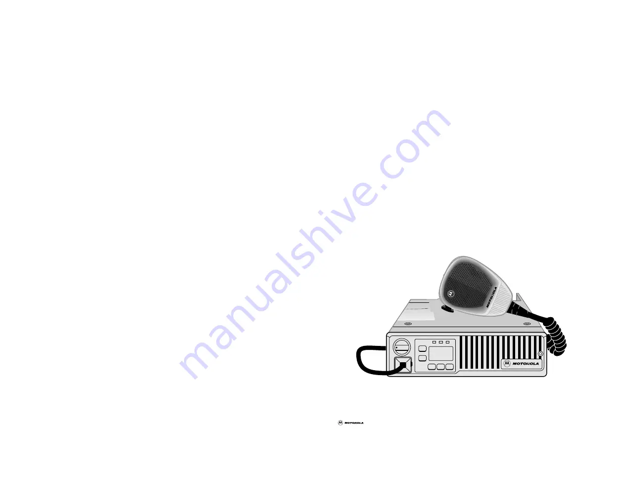
MaxTrac
MaxTrac 100
TM
/MaxTrac 300
Mobile Radios
Motorola8000 West Sunrise BoulevardFort Lauderdale, Florida 33322
68P80901Z04-A
*6880901Z04-A*
Page 1: ...M MaxTrac MaxTrac 100TM MaxTrac 300TM Mobile Radios Motorola 8000 West Sunrise Boulevard Fort Lauderdale Florida 33322 68P80901Z04 A 6880901Z04 A ...
Page 2: ...M MaxTrac operating instructions ...
Page 3: ...g an Emergency Alert 11 Display of Incoming Identification Numbers 11 Activating the Call List for Sending Selective Messages 12 Selecting Call List Letters and ID Numbers 12 Sending a Signalling Message 12 Receiving an Acknowledgement 13 Exiting the Call List 13 Receiving an Emergency Alarm 13 Clearing an Emergency Alarm 13 Channel ScanTM Feature MaxTrac 300 16 32 Channel Radios Only 14 Descripti...
Page 4: ...try 23 Installation Planning Mobile Radios 24 Installation Planning Base Control Stations 24 Recommended Tools for Installation 24 Antenna Mounting 24 Radio Mounting 25 Begin Installation 26 DC Power Cable Installation 26 Non Locking Trunnion Installation 28 Sleeve Mounting Bracket Installation 30 Service 32 Related Publications 32 Product Service Information 33 Parts Information 33 Computer Softw...
Page 5: ...C D Performance optional extra stability mounting required on some models MaxTrac High Performance Compact Microphone with Hardware Non Locking Trunnion or Sleeve Mounting Bracket with Hardware 10 Foot Power Cable 12Vdc Negative Ground 3 Watt Internal Speaker Rotary Volume Control Time Out Timer On Hook Monitor Capability Mini UHF Antenna Connector MaxTrac 300TM 32 Channel Features The MaxTrac 300...
Page 6: ...ly Identical to the way the Select button is used on the other models The H L button is pressed once to enable the external alarm horn lights feature pressing the H L button again or pressing the Call button will turn the external alarm feature off On other models the Select button is used to enable this feature the Select and or Exit button is used to turn it off Other operational differences for...
Page 7: ...ordered as an option on all models MDC 1200 and Quik Call II signalling packages are optional on all models except for 32 channel models The 32 channel models ship standard from the factory with Quik Call II signalling enabled On signalling equipped models the radio service software RSS can be used to enable and disable different features Contact your Motorola representative or contact your local ...
Page 8: ...vehicle battery Radio Self Check Every time the radio is turned on power up it performs a functional self check and if necessary will sound a 5 second warning tone instead of the short chirp tone normally heard at power up This is an indication that the radio is no longer operating at the exact parameters set in the factory or field and should be serviced immediately 6 MaxTrac 100 300 Operation Tu...
Page 9: ...a Channel If you wish to monitor a channel press the monitor button Monitor on MaxTrac 100 radio or Mon on MaxTrac 300 radio to disable coded squelch You may also enable the monitor function by taking the microphone off the hook When in the monitor mode the monitor Mon LED will light steadily Unsquelching the Radio To unsquelch the radio press the monitor button Monitor on MaxTrac 100 radio or Mon...
Page 10: ...LED Bsy on MaxTrac 100 radio or Tx Bsy on MaxTrac 300 radio will flash if there is another carrier on the channel If the channel is clear press the PTT push to talk button on the side of the microphone On the MaxTrac 100 radio the channel indicator LED F1 or F2 will turn red to indicate that you are on the air On the MaxTrac 300 radio the transmit LED Tx Bsy will light steadily to indicate that yo...
Page 11: ...hat channel when the selective call is sent It is recommended that priority scan is selected and the signalling channel be designated a priority channel to improve the likelihood that the selective call will be received Receiving a Voice Selective Call When a voice selective call is received a one time two beep alert tone will sound the busy and monitor LEDs will flash On a MaxTrac 300 radio the d...
Page 12: ... the external alarm armed mode if enabled MaxTrac 100 MaxTrac 300 16 32 Channel MaxTrac 100 MaxTrac 300 16 32 Channel Mode Monitor F1 F2 Mon Bsy Mon Scan Select Tx Bsy Mon Pri Pri Usr Scan Receiving an External Alarm Horn or Lights The external alarm horn or lights feature requires an alarm relay cable To enable this feature press the Select button on a MaxTrac 300 radio H L button on 900MHz 6 cha...
Page 13: ... control unit has received and acknowledged the emergency The EE will then disappear from the display MaxTrac 300 radio only Messages will be heard over the radio s speaker during the emergency MaxTrac 300 Monitor and busy LEDs will function normally during the emergency The only way to cancel the emergency is by pressing the push to talk PTT No other button press will function normally except mon...
Page 14: ...Pri Usr Scan Mon Call H L Tx Bsy Mon Selecting Call List Letters and ID Numbers Each press of the Select button Call button on 900MHz 6 channel model causes the display to move down the list of call letters which have been programmed in the radio Pressing the Up or Down buttons will scroll through the ID numbers All call list ID numbers will be displayed with each set of call letters However some ...
Page 15: ...s of the Exit or H L button will take the radio out of signalling and return to the channel display at any time Receiving an Emergency Alarm When an emergency alarm is received by the control unit an alert tone will sound The display will alternate EE and the ID number of the radio sending the emergency Five different emergency IDs can be queued However the first ID to be received will be displaye...
Page 16: ...y user scan Both types of scan operate in either non priority or priority modes Non priority scan means that every channel on the scan list is monitored equally However with priority scan certain channels have priority over others and are checked more frequently If you are scanning with priority the radio will continually check for activity on your priority channels even when you are listening to ...
Page 17: ...an mode when the power is turned off the radio will return to the scan mode when powered up again To leave scan press the Scan button To respond to scanned channel activity lift the microphone off hook The radio will suspend scanning and return to the channel displayed before entering scan If you wish to respond to a transmission on another channel you must use the Up or Down buttons to reach that...
Page 18: ...and will be retained in memory until changed or deleted This is separate from the scan lists pre programmed to each active channel To create or modify the user scan list hold the Scan button down for 2 seconds until you hear a second chirp tone The channel number will flash Add or delete this channel from the list by pressing the Select button Pre Programmed Scan A vertical segment in the upper le...
Page 19: ...dio to be continually monitoring that channel you may wish to temporarily eliminate that channel from the scan list without reprogramming the radio When receiving a transmission on that channel simply hold down the Select button for 2 seconds and the nuisance channel will be temporarily deleted until that scan mode is changed or exited Priority channels and the home channel cannot be deleted Scan ...
Page 20: ...o service software RSS The time out timer can be disabled or changed to any duration from 1 to 255 seconds The default setting is 30 seconds Scanning radios can also be programmed to enable talk back scan or the priority sample rate can be changed Finally radios ordered with selective signalling and 16 pin expanded accessory connector can be programmed to include a wide variety of features and acc...
Page 21: ...a radio transmitter must be maintained within specified limits Specifically FCC Part 90 215 states that the licensee of each station shall employ a suitable procedure to determine that the carrier frequency of each transmitter authorized to operate with an output power in excess of two watts is maintained within the tolerance prescribed in 90 213 It is recommended therefore that these three parame...
Page 22: ...le is within 2 feet 0 6 meter of the antenna DO NOT operate the transmitter of a fixed radio base station microwave rural telephone RF equipment or marine radio when someone is within 2 feet 0 6 meter of the antenna DO NOT operate the transmitter of any radio unless all RF connectors are secure and any open connectors are properly terminated TURN THE RADIO OFF when near electrical blasting caps or...
Page 23: ...a power output in excess of 7 watts do not install any type of antenna closer than 2 feet from any occupant of the vehicle Failure to follow this procedure may result in the exposure of the vehicle occupants to radio frequency energy levels higher than recommended by the FCC Metal Body Vehicles In metal body vehicles with transmitters at any frequency having a power output in excess of 7 watts it ...
Page 24: ...the interior of the vehicles This standard requires that 1 Any space containing radio equipment shall be isolated by a seal from the space in which the LP gas container and its fittings are located 2 Remote outside fitting connections shall be used 3 The container space shall be vented to the outside CAUTION Unsafe use of converted mobile radio equipment for portable applications Motorola two way ...
Page 25: ...y different from 50 ohms This protection circuitry significantly enhances the radio s reliability with minimal performance degradation If you check transmitter output power levels during installation be sure you are using a good 50 ohm load with a minimum of adapters and using short test cables Any load variation from 50 ohms may cause an apparent reduction in output power due to the normal operat...
Page 26: ... enters the building Be sure 117Vac 60Hz power is available Make sure sufficient air can flow around the radio to permit adequate cooling Recommended Tools for Installation The following tools are recommended for proper installation of your new radio Portable Drill Hammer Center Punch 5 16 Hex Nut Driver 1 4 Hex Nut Driver Phillips 2 Screwdriver TORX Screwdriver T25 3 8 Diameter Drill Bit 5 16 Dia...
Page 27: ...surface you may need to supply and install shim washers not provided between the bracket and the mounting surface Shims are necessary to tilt the radio because the heavy duty bracket blocks the standard trunnion adjustments Follow instructions provided with the option Note The extra stability mounting tray is not necessary for low band 35 watt 800MHz or 30 watt 900MHz models as the sleeve mounting...
Page 28: ... the following manner 1 Determine a routing plan for the power cable with reference to where the radio is to be mounted 2 Locate an existing hole with a grommet in the vehicle fire wall or drill a 3 8 access hole at the location for passing the power cable into the engine compartment Install a grommet with 1 4 internal diameter in the access hole to avoid damage to the cable CAUTION A high degree ...
Page 29: ...Connect the fuse holder red adapter lead plug to the mating receptacle on the red lead of the power cable as shown in Figure 2 FUSE COVER RED LEAD RED MTG HOLE MOLDED IN LINE FUSE HOLDER TO VEHICLE CHASSIS GROUND ENGINE COMPARTMENT TO BATTERY ADAPTER FIREWALL RED LEAD BLACK LEAD RING LUGS Figure 2 DC Power Cable Assembly 7 Connect the power cable black lead directly to the vehicle chassis ground 8...
Page 30: ...o the surface with the four 10 16x3 4 screws provided 5 Place the radio in the trunnion mounting bracket and secure it with the two thumb screws provided 6 To complete your radio installation plug the power cable into the radio power connector see Figure 3 7 Mount the antenna using the instructions provided with the antenna kit Run the coaxial cable to the radio mounting location If necessary cut ...
Page 31: ...dio microphone in the same manner you connect and disconnect your telephone handset TRUNNION MOUNTING BRACKET TAB TAB BELOW DASH MOUNTING MOUNTING SURFACE TAB THUMB SCREW 2 TRANSMISSION HUMP MOUNTING TAB THUMB SCREW 2 SHEET METAL SCREWS MOUNTING SURFACE NOTE Consult your Motorola Representative for Overhead Mounting Precautions Figure 4 Trunnion Mount for Radio Note Consult your Motorola Represent...
Page 32: ... Install the tapered stud and nut in the rear hole of the sleeve mounting bracket as shown in Figure 5 7 Insert the radio into the sleeve mounting bracket guiding the tapered pin into the hole in the rear of the heat sink Secure it with the two thumb screws provided If you have skipped step 6 above install the M5 x 0 8 x 10mm TORX screw in the rear of the bracket to secure the radio 8 To complete ...
Page 33: ...tion cont 31 Sleeve Mounting Bracket Installation cont 31 TORX SCREW M5X 8X10 NUT HEX M5X 8 TAPERED STUD SLEEVE MOUNTING BRACKET MOUNTING SURFACE SLEEVE MOUNTING BRACKET THUMB SCREW MOUNTING SURFACE Figure 5 Sleeve Mount for Radio ...
Page 34: ... independent distributor service organizations For a contract service agreement please contact your nearest Motorola service representative authorized Motorola dealer or Motorola sales representative If you suspect a radio problem check the following items before requesting service 1 Radio Checks Be sure the radio is turned on and passes the radio self check 2 Operating Instructions Review your op...
Page 35: ... pm CST Monday Friday Chicago U S A Domestic U S A 1 800 422 4210 1 800 826 1913 Federal Government TELEX 280127 FAX 1 708 538 8198 FAX 1 301 925 2690 Federal Government Domestic U S A after hours or weekends 1 800 325 4036 or 1 708 576 5111 International 1 708 576 9271 TELEX 403305 MOTO PART SHBU UD FAX 1 708 576 3023 TWX 910 693 0869 No international weekend service is available Parts Informatio...
Page 36: ...sive right to copy or reproduce in any form the copyrighted computer program Accordingly any copyrighted Motorola computer programs contained in the Motorola equipment described in this manual may not be copied or reproduced in any manner without the express permission of Motorola Furthermore the purchase of Motorola equipment shall not be deemed to grant either directly or by implication estoppel...
Page 37: ...M MaxTrac MaxTrac 100TM MaxTrac 300TM Mobile Radios Motorola 8000 West Sunrise Boulevard Fort Lauderdale Florida 33322 68P80901Z04 A 6880901Z04 A ...