M68360QUADS-040 Hardware User’s Manual
SUPPORT INFORMATION
56
FIGURE B-1 Host Computer (ADI) to M68360QUADS-040 Connection
B.3.1
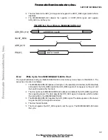
Write Cycle from Host to M68360QUADS-040
The application software in the Host uses the handshake signals to coordinate data transfer across the
parallel link. The QUICC040bug software in the M68360QUADS-040 is responsible for accepting the data
and responding to the handshake signals. The signals are shown in FIGURE B-2.
The sequence of events during a byte write to the M68360QUADS-040 is as follows:
1.
The Host selects the M68360QUADS-040 board by putting the board’s address on the
ADS_SEL(0:2) signals.
2.
The Host places a data byte in the data bus latch (buffer is in high-impedance state).
3.
The Host asserts the HOST_REQ signal (the data buffer is enabled, data appears on the
bus).
4.
The M68360QUADS-040 detects the HOST_REQ signal and reads the data byte.
5.
The M68360QUADS-040 asserts the ADS_ACK signal.
HOST_REQ
ADS_ACK
ADS_REQ
HST_ACK
ADS_BRK
HOST_BRK~
ADS_INT
INT_ACK
ADS_RESET
ADS_ALL
ADS_SEL(0:2)
PD(0:7)
HOST_ENABLE~
HOST_VCC
M68360QUADS-040
ADI board
HOST
COMPUTER
F
re
e
sc
a
le
S
e
m
ic
o
n
d
u
c
to
r,
I
Freescale Semiconductor, Inc.
For More Information On This Product,
Go to: www.freescale.com
n
c
.
..


