


98-08901C67-O
11
Developer Board and Interfaces Description
3.3
INITIAL SETUP
This section describes the initial procedure for setting up the g20 Developer Board for testing and evaluating of the g20. The
tasks in this section need to be performed only once, before the first time you use the g20 Developer’s Kit. After performing the
initial setup, you can modify the default settings or use different peripheral devices, as described in “Configuration” on page 14.
Perform the steps in this section in sequence.
Before starting, remove the cover of the Developer Board. The cover simply slides up off the board, and does not require the
removal of any screws or clips. After setting up the Developer Board, you can place the cover back on the Developer Board by
simply pushing it gently back into place. Make sure the cover is aligned properly with the external connectors on the side of the
board.
3.3.1
g20
The Developer Board works with all versions of the g20. There are four versions of the g20:
• European version
• European version with USB driver
• North American version
• North American version with USB driver
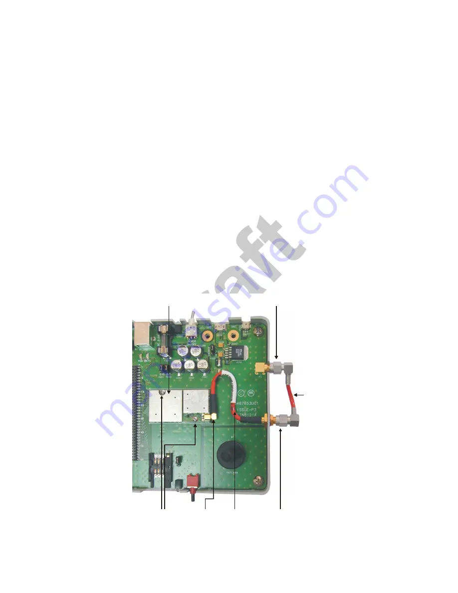
Connect the g20 to the Developer Board by performing the following steps:
• Place the g20 into the area on the Developer Board marked by a white rectangle, and push the g20 70-pin connector down
into the UUT 70-pin connector (P1). The two screw holes on the g20 should be aligned with the g20 spacers (M2 and M3).
• Fasten the g20 to the Developer Board using the two M2 screws provided with the kit.
Figure 8. Connecting the g20
External Antenna
Connector
RF
Cable
MMCX
Connector
g20
Screws
Internal Antenna
Connector
RF Cable
g20
Summary of Contents for F3030A
Page 1: ...D r a f t Developer s Guide Motorola g20 Developer s Kit 98 08901C67 O ...
Page 2: ...ii 98 08901C67 O REVISION HISTORY Revision Date Purpose ...
Page 10: ...Preface 4 98 08901C67 O ...
Page 42: ...Developer Board and Interfaces Description 36 98 08901C67 O ...
Page 44: ...Mechanical Description 38 98 08901C67 O ...
Page 48: ...Service Support 42 98 08901C67 O ...
Page 51: ...98 08901C67 O 45 Schematics Placement and Parts List Figure 24 Diagnostics ...
Page 52: ...Schematics Placement and Parts List 46 98 08901C67 O Figure 25 Power ...
Page 53: ...98 08901C67 O 47 Schematics Placement and Parts List Figure 26 Debug Interface ...
Page 54: ...Schematics Placement and Parts List 48 98 08901C67 O Figure 27 Keypad and Display ...
Page 55: ...98 08901C67 O 49 Schematics Placement and Parts List Figure 28 Audio Interface ...
Page 56: ...Schematics Placement and Parts List 50 98 08901C67 O Figure 29 LEDs ...
Page 57: ...98 08901C67 O 51 Schematics Placement and Parts List Figure 30 Battery Charger ...
Page 58: ...Schematics Placement and Parts List 52 98 08901C67 O Figure 31 Serial Interface ...
Page 68: ...Schematics Placement and Parts List 62 98 08901C67 O ...
Page 72: ...Index 66 98 08901C64 O ...