


DMA Control Registers 5–0 (DCR[5–0])
4
-36
DSP56303 User’s Manual
15–11
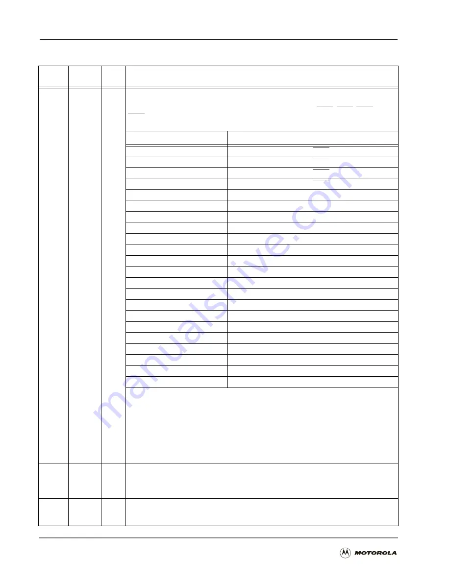
DRS[4–0]
0
DMA Request Source
Encodes the source of DMA requests that trigger the DMA transfers. The DMA request
sources may be external devices requesting service through the IRQA, IRQB, IRQC and
IRQD pins, triggering by transfers done from a DMA channel, or transfers from the internal
peripherals. All the request sources behave as edge-triggered synchronous inputs.
DRS[4–0]
Requesting Device
00000
External (IRQA pin)
00001
External (IRQB pin)
00010
External (IRQC pin)
00011
External (IRQD pin)
00100
Transfer done from channel 0
00101
Transfer done from channel 1
00110
Transfer done from channel 2
00111
Transfer done from channel 3
01000
Transfer done from channel 4
01001
Transfer done from channel 5
01010
ESSI0 receive data (RDF0 = 1)
01011
ESSI0 transmit data (TDE0 = 1)
01100
ESSI1 receive data (RDF1 = 1)
01101
ESSI1 transmit data (TDE1 = 1)
01110
SCI receive data (RDRF = 1)
01111
SCI transmit data (TDRE = 1)
10000
Timer0 (TCF0 = 1)
10001
Timer1 (TCF1 = 1)
10010
Timer2 (TCF2 = 1)
10011
Host receive data full (HRDF = 1)
10100
Host transmit data empty (HTDE = 1)
10101–11111
Reserved
Peripheral requests 18–21 (DRS[4–0] = 111xx) can serve as fast request sources. Unlike a
regular peripheral request in which the peripheral can not generate a second request until
the first one is served, a fast peripheral has a full duplex handshake to the DMA, enabling a
maximum throughput of a trigger every two clock cycles. This mode is functional only in the
Word Transfer mode (that is, DTM = 001 or 101). In the Fast Request mode, the DMA sets
an enable line to the peripheral. If required, the peripheral can send the DMA a one cycle
triggering pulse. This pulse resets the enable line. If the DMA decides by the priority
algorithm that this trigger will be served in the next cycle, the enable line is set again, even
before the corresponding register in the peripheral is accessed.
10
D3D
0
Three-Dimensional Mode
Indicates whether a DMA channel is currently using three-dimensional (D3D = 1) or
non-three-dimensional (D3D = 0) addressing modes. The addressing modes are specified by
the DAM bits.
9–4
DAM[5–0]
0
DMA Address Mode
Defines the address generation mode for the DMA transfer. These bits are encoded in two
different ways according to the D3D bit.
Table 4-11. DMA Control Register (DCR) Bit Definitions (Continued)
Bit
Number
Bit Name
Reset
Value
Description
Summary of Contents for DSP56303
Page 1: ...DSP56303 User s Manual 24 Bit Digital Signal Processor DSP56303UM AD Revision 1 January 2001 ...
Page 52: ...JTAG OnCE Interface 2 22 DSP56303 User s Manual ...
Page 114: ...General Purpose Input Output GPIO 5 10 DSP56303 User s Manual ...
Page 212: ...GPIO Signals and Registers 8 26 DSP56303 User s Manual ...
Page 268: ...Interrupt Equates A 22 DSP56303 User s Manual ...
Page 306: ...Programming Sheets B 38 DSP56303 User s Manual ...
Page 320: ...Index 14 DSP56303 User s Manual ...