MOTOROLA CONFIDENTIAL - PROPRIETARY
6881036B20
November 20, 2000
41
Level 3 Service Manual
Troubleshooting
000784-O
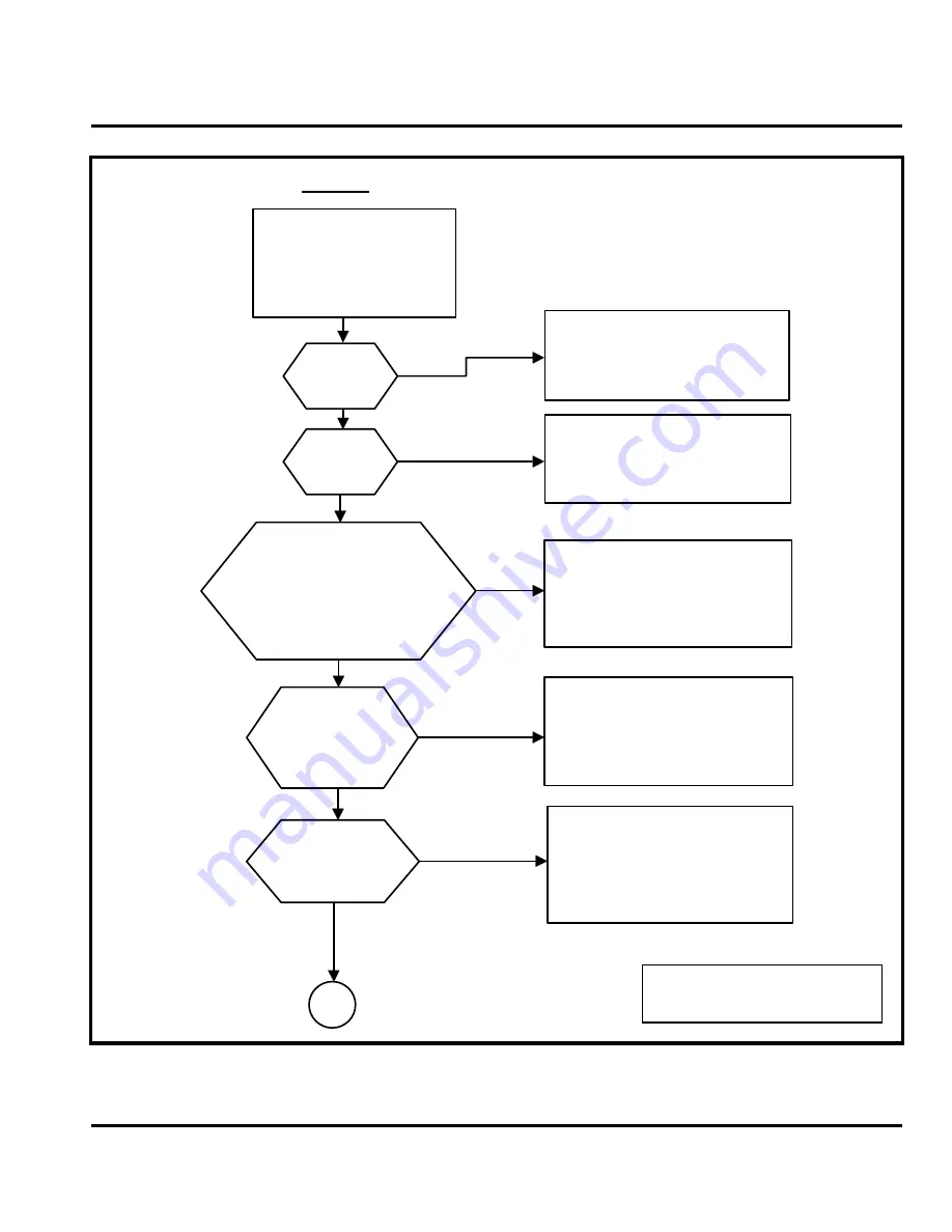
Figure 25. Device Will Not Power Up (Sheet 1 of 2)
1. Download EMMI box with the
correct software.
2. Attach UUT to EMMI box via
J600.
3. Connect EXT B+ (4.5V) to UUT.
4. Verify UUT loads software.
1. Flash the Language and Flexing.
2. Perform complete test.
UUT powers up
correctly
B+ is present
on
C915
?
1. Place temporary short across
R943
.
2. Verify following voltages:
V_BOOST: 5.6V (
C913
)
V1: 5V (
C906
)
V2: 2.7V (
C939
)
V3: 1.87V (
C910
)
V_REF: 2.8V (
C919
)
1. For incorrect V_BOOST, check in order:
L901
,
CR902
,
R904
, and
U900
.
2. For other incorrect voltages, check for
shorts to ground and check
U900
.
See Note 1
26 MHz signal is present
on
R244
(near
U200
)?
RF_V1 is present on
Q201
(2.7V at
C217
)
and RF_V2 is present on
Q202
(2.7V at
C215
)?
No: check
Q201
,
Q202
, and
U200
.
Yes: check
Y200
and
U200
.
See Note 1
13 MHz clock is present on
C225
?
No: check
CR248
and associated
components.
Yes: check
U200
.
See Note 1
A
YES
NO
YES
NO
YES
NO
YES
YES
NO
NO
START
1. Check EXT B+ line from
J600
to
CR903
.
2. Check
CR903
and
Q905
.
See Note 1
13 MHz signal is present
on
R238
(near
U200
)?
Note 1: Check components for correct
orientation, cold solder joints, physical
damage, and functionallity.
Summary of Contents for 38C V100
Page 1: ...Level 3 Service Manual Model V100 GSM Technology Product Family 38C Personal Communicator ...
Page 2: ......
Page 73: ...V100 BOARD LAYOUT PAGE 1 2 ...
Page 74: ...V100 BOARD LAYOUT PAGE 2 2 ...
Page 77: ...V100 CONNECTOR SCHEMATICS ...
Page 78: ...V100 DISPLAY SCHEMATICS ...
Page 79: ...V100 FM SCHEMATICS ...
Page 81: ......
Page 83: ......


