


USER
MANUAL
www.motoplat.nl
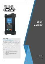
VC-3.1
The VC-3.1 is a sturdy looking handheld tester and analyzer
that can stand rough handling. Combining all functions and
possibilities of our other handheld testers, the VC-3.1 is
unique in its kind. Detailed specifications are outlined below.
Detailed specifications are outlined below.
Specifications
o
On-car testing
o
Operates on conventional test equipment
o
Static testing
o
Built-in 19 volt lithium ion battery pack
o
User-friendly
All-in-one handheld tester
ENGLISH
VERSION 2020