background image

26/1

1/08  C0DN6000_EN

ENGLISH

ENGLISH

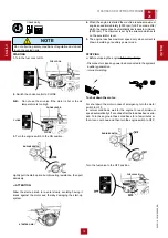
PUSH AND
TWIST

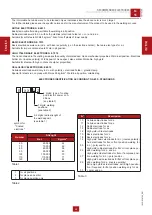
CONNECT WELDING CABLES

Insert the welding cable plugs completely in the sockets, turning 

clockwise to lock them in place.

Connect the earth clamp to the negative pole and the electrode 

holder to the positive.

+

 Pay attention to the two polarities on the welding circuit, 

which must not come into electrical contact with each other.

-  Carefully tighten the output cables to the bushings; if loose, 

they can cause problems of overheating and damage the 

bushings, cables, etc.

-  Make certain the grounding pincer is connected as near as 

possible to the work station.

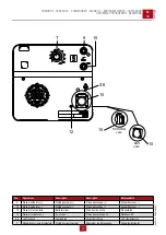
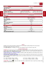
ADJUSTING THE WELDING CURRENT

The welding current is regulated by turning knob “T” conti-

nuously. If set to the minimum (turned fully in an anticlockwise 

direction) it provides a current of approximately 30 A; if set to 

the maximum (turned fully in a clockwise direction) it gives a 

maximum current of approximately 200A (20V).

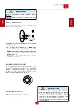
RECOMMENDED ELECTRODES

All the electrodes on the market can be used.

M

34

USE AS A WELDER

REV
.0-12/19

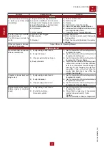
WARNING

A

reas for which access by non-authorized personnel is 

forbidden

 are:

- the control panel (at the front) - the endothermic motor 

discharge.

!

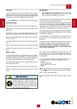
ATTENTION

To reduce the risk of electromagnetic interference, keep the 

welding cable length short and keep them on or near the 

ground. If possible, welding operations should not be done 

near sensitive electronic devices. If interference continues 

to occur, adopt additional measures: shift the group, use 

shielded cables, line filters, shield the entire work area.

If the above solutions do not suffice, consult our Technical 

Servicing Department.

!

20

Summary of Contents for MAGIC WELD 200

Page 1: ...dition dition Edici n Ausgabe Edi o C0DN60009003 Motosaldatrice EngineDrivenWelder Motosoudeuse Motosoldadoras Schwei aggregat Motosoldadora 12 2019 COMPACT WELDERS MAGIC WELD 200 STAGE V USE AND MAIN...

Page 2: ......

Page 3: ...PAG 14 3 INSTALLATION AND USE M2 7 INSTALLATION AND DIMENSIONS PAG 15 M2 6 INSTALLATION AND ADVICE PAG 16 M25 SET UP FOR OPERATION ENGINE PAG 17 M26 STARTING AND STOPPING PAG 18 M31 CONTROLS PAG 19 M3...

Page 4: ...must also given to him Do not damage it do not take parts away do not tear pages and keep it in places protected from dampness and heat You must take into account that some figures contained in it wan...

Page 5: ...Driven Welder complies with its requirements 6 Welding process symbol 7 Symbol for Engine Driven Welders which can be used an environment with increased risk of electric shock 8 Welding current symbol...

Page 6: ...amage can happen to persons or things HIGH VOLTAGE Attention High Voltage There can be parts in voltage dangerous to touch The non observance of the advice implies life danger FIRE Danger of flame or...

Page 7: ...octor Suction of liquids from lungs If you suppose that vomit has entered the lungs as in case of spontaneous vomit take the subject to the hospital with the utmost urgency Inhalation In case of expos...

Page 8: ...en and pets so as to protect them from pos sible injury caused by any part of the machine SAFETY PRECAUTIONS DURING HANDLING AND TRAN SPORTATION Lift the machine using only the points allocated for th...

Page 9: ...nal on the front of the machine Do not use the machine with wet or damp hands and or clothing Use plugs suitable for the output sockets of the machine and make sure that electrical cords are in good c...

Page 10: ...intenance or repair Do not refuel while the engine is running or hot Do not smoke or use naked flames when refueling Refuel only outdoors or in well ventilated areas Avoid spilling fuel especially on...

Page 11: ...rea If adequancy of ventilation or exhaust is uncertain have the air quality checked Arc rays can burn eyes and skin Use welding helmet with correct shade of filter While working protect your eyes usi...

Page 12: ...ermic engine it is composed of various parts such as engine alternator electric and electronic controls the fairing at a protective structure The assembling is made on a steel structure on which are p...

Page 13: ...machine is necessary to record some data Please write the requested data inside the squares to side 1 Model of machine 2 Serial number of the machine 3 Serial number of the engine 4 Name of the deale...

Page 14: ...liminating the packing materials the User must keep to the norms in force in his country 1 Take the machine C out of the shipment packing Take out of the envelope A the user s manual B 2 Fit the handl...

Page 15: ...12 19 C0DN6000_IT M 2 7 IINSTALLAZIONE E DIMENSIONI INSTALLATION AND DIMENSIONS INSTALLATION ET DIMENSIONS LUFTZIRKULATION UND ABMESSUNGEN INSTALACI N Y DIMENSIONES INSTALA O E DIMENS ES REV 0 12 19...

Page 16: ...cipitation unless sheltered M 2 6 INSTALLATION adviceS ENGINE DRIVEN WELDER REV 0 09 18 DANGER The machine must be positioned so that exhaust gas is dif fused without being inhaled by any living being...

Page 17: ...s below the safety limit If the motor does not start up again after shutting itself off check the oil level Oil fill tap dip stick Upper oil level FUEL Fill the tank with gasoline for automobiles pref...

Page 18: ...tomatically decreases to minimum 2000 rpm The minimum is set by the solenoid which acts on the accelerator lever 5 The engine reaches maximum speed only when current is drawn in welding or auxiliary p...

Page 19: ...Prese di saldatura Welding sockets Prises de soudage Schwei buchse 12 Presa di messa a terra Earth terminal Prise de mise terre Erdanschlu 15 Presa di corrente in c c d c socket Prises de courant en c...

Page 20: ...set to the minimum turned fully in an anticlockwise direction it provides a current of approximately 30 A if set to the maximum turned fully in a clockwise direction it gives a maximum current of appr...

Page 21: ...pm Minimum welding voltage TOO LOW From Fig 1 proceed as follows when the machine idles engine cold Keep pin A locked 8 mm spanner and unscrew nut B 7 mm spanner Again with pinAlocked turn nut C clock...

Page 22: ...ther the board or the current sensor is changed it is necessary to check the max welding current and if it is the case to set it as follows Attach de pcb on his iron plate connect all wives and all co...

Page 23: ...split at the first crease Using double insulated equipment is advisable this is identifiable by the symbol and for having no earth facility If the machine is designed to supply circuits which are par...

Page 24: ...x 55 kg mm2 Weld in all position volatile slag ELECTRODES IDENTIFICATION ACCORDING TO A W S STANDARDS E X X Y Z 2 digits type of coating and electric power con ditions see table 3 1 digits welding pos...

Page 25: ...1 Faulty welding control board 2 Faulty Hall sensor 3 Chopper welding bridge broken 4 Faulty alternator 1 Ask for intervention of Service Department to replace the board 2 Ask for intervention of Ser...

Page 26: ...0 Value measured alternating the cables AUXILIARY POWER GENERATION CIRCUIT No current under no load con ditions in auxiliary power mode 1 Auxiliary power diode bridge broken 2 Faulty inverter 3 Faulty...

Page 27: ...ALS AND LABELS All warning and decals should be checked once a year and replaced if missing or unreadable STRENUOUS OPERATING CONDITIONS Under extreme operating conditions frequent stops and starts du...

Page 28: ...d or dispositions in force in the place M 45 STORAGE and disassEmble REV 0 06 00 DISASSEMBLE Have qualified personnel disassemble the machine and dispose of the parts including the oil fuel etc in a c...

Page 29: ...level It s admitted overload of 10 each hour every 12 h In an approximative way one reduces of 1 every 100 m altitude and of 2 5 for every 5 C above 25 C ACOUSTIC POWER LEVEL ATTENTION The concrete r...

Page 30: ...e H3 Bougie allumage W6 Senseur de hall R8 Inverteur S8 Voyant Surcharge A Generator H Steckdose 230V 1 phasig I Steckdose 110V 1 phasig R Steuerplatine Schwei strom T Schwei stromregler Y Diodenbr ck...

Page 31: ...02 12 19 C0DN6000_IT M 61 SCHEMA ELETTRICO ELECTRIC DIAGRAM SCHEMA ELECTRIQUES ESQUEMA EL CTRIQUE STROMLAUFPLAN ESQUEMA EL TRICO ELEKTRISCHE REGELING 230V Version REV 0 12 19 31...

Page 32: ...02 12 19 C0DN6000_IT M 61 SCHEMA ELETTRICO ELECTRIC DIAGRAM SCHEMA ELECTRIQUES ESQUEMA EL CTRIQUE STROMLAUFPLAN ESQUEMA EL TRICO ELEKTRISCHE REGELING 110V Version REV 0 12 19 32...

Page 33: ...11 01 01 Note NOTE 33...

Page 34: ...11 01 01 Note NOTE 34...

Page 35: ......

Page 36: ...MOSA div della BCS S p A Viale Europa 59 20090 Cusago Milano Italy Tel 39 0290352 1 Fax 39 0290390466 www mosa it...

Reviews: