background image

CONTENTS

E  :

PREPARATION BEFORE STARTING MASS PRODUCTION

1

CONDITIONS FOR STARTING AUTOMATIC OPERATION. . . . . . . . . . . . . . . . . . . . . . E-1

2

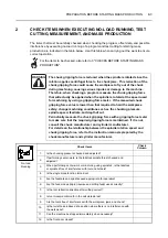
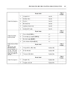
CHECK ITEMS WHEN EXECUTING NO-LOAD RUNNING, 
TEST CUTTING, MEASUREMENT, AND MASS PRODUCTION . . . . . . . . . . . . . . . . . . E-3

3

CHECKS BEFORE STARTING MASS PRODUCTION  . . . . . . . . . . . . . . . . . . . . . . . . . E-6

4

PROGRAM CHECK  . . . . . . . . . . . . . . . . . . . . . . . . . . . . . . . . . . . . . . . . . . . . . . . . . . . . E-8

4-1

Preparations for Checking a Program . . . . . . . . . . . . . . . . . . . . . . . . . . . . . . . . . . E-8

5

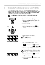
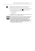
CHECKING A PROGRAM USING MACHINE LOCK FUNCTION  . . . . . . . . . . . . . . . . . E-9

6

CHECKING A PROGRAM WITHOUT CHUCKING A WORKPIECE  . . . . . . . . . . . . . . E-12

6-1

Precautions on Using the Spindle OFF Mode Function  . . . . . . . . . . . . . . . . . . . E-13

6-2

Checking a Program by Using the Spindle OFF Mode Function. . . . . . . . . . . . . E-14

7

CHECKING THE PROGRAM WITH A WORKPIECE CLAMPED IN THE CHUCK  . . . E-18

8

TO FINISH A WORKPIECE WITHIN THE SPECIFIED TOLERANCE 
WITH THE TOOL WEAR OFFSET FUNCTION (TEST CUTTING)  . . . . . . . . . . . . . . . E-23

9

SETTING THE INHIBITED TOOL ENTRY ZONE . . . . . . . . . . . . . . . . . . . . . . . . . . . . . E-28

10 REMOVING CHIPS ENTANGLING WORKPIECE . . . . . . . . . . . . . . . . . . . . . . . . . . . . E-29

11 OPERATION PROCEDURE FOR DIFFERENT TYPES OF MACHINING . . . . . . . . . . E-31

11-1 Chuck Work Operation  . . . . . . . . . . . . . . . . . . . . . . . . . . . . . . . . . . . . . . . . . . . . E-31

11-2 Center-work Operation (Tailstock Specification) . . . . . . . . . . . . . . . . . . . . . . . . . E-32

11-3 Both-center-work Operation (Tailstock Specification) . . . . . . . . . . . . . . . . . . . . . E-33

12 WORK COUNTER/TOTAL COUNTER SETTING (OPTION) . . . . . . . . . . . . . . . . . . . . E-34

12-1 Work Counter (Option)  . . . . . . . . . . . . . . . . . . . . . . . . . . . . . . . . . . . . . . . . . . . . E-34
12-2 Total Counter (Option) . . . . . . . . . . . . . . . . . . . . . . . . . . . . . . . . . . . . . . . . . . . . . E-36

Summary of Contents for NZ-S1500

Page 1: ...programming carefully read the manuals supplied by Mori Seiki the NC unit manufacturer and equipment manufacturers so that you fully understand the information they contain Keep the manuals carefully...

Page 2: ...these points before using the machine Mori Seiki will not be liable for any damages occurring as a direct or indirect consequence of using the machine without clarifying these points All rights reserv...

Page 3: ...DISPLAY ON TURNING ON POWER PREFACE FLOW UNTIL THE PRODUCT IS COMPLETED DOOR INTERLOCK FUNCTION A OPERATION PANELS B MANUAL OPERATION C CHUCKING D SETTING OF COORDINATE SYSTEM E PREPARATION BEFORE STA...

Page 4: ...t be strictly observed Other symbols The format identified by this symbol gives information for programming Indicates the items that must be taken into consideration Indicates useful guidance relating...

Page 5: ...2 Lamp indication Indicates that the indicator is lit Indicates that the indicator is blinking...

Page 6: ...ared by Mori Seiki 2 Instruction Manual prepared by Mori Seiki MAINTENANCE MANUAL OPERATION MANUAL PROGRAMMING MANUAL 3 NC unit Operation and Maintenance Manuals prepared by the NC unit manufacturer 4...

Page 7: ...sonnel who maintain and inspect a machine tool or safety device or safety measures provided with it and the programmers who create programs used for machining who are engaged in operations which deal...

Page 8: ...uries Contact Mori Seiki the NC unit manufacturer or the relevant equipment manufacturer immediately if the protective cover or safety devices are damaged 4 Always lock out the power to the machine be...

Page 9: ...rating the machine check the area where you will have to stand and walk to make sure you can operate the machine safely If you do not check your footing beforehand you could loose your balance while w...

Page 10: ...e 8 Always observe the instructions in the caution labels stuck to the machine Carefully read the Safety Guidelines supplied with the machine so that you fully understand them If the writing on the la...

Page 11: ...st other hazards For example each machine user will machine a variety of workpiece types and use a variety of workpiece holding fixtures cutting tools and cutting conditions you are still responsible...

Page 12: ...k spindle center when the tailstock spindle is extended After making this adjustment clamp the tailstock body to the bed If the tailstock body is not clamped to the bed or if the position of the tails...

Page 13: ...ant when operating the machine and an inability to make such confirmations properly could cause accidents involving serious injuries or damage to the machine 6 Ensure that the workplace is adequately...

Page 14: ...an remove chips and foreign matter near the machine If left chips and foreign matter may cause plant personnel to fall and injure themselves 10 Use a working bench strong and stable enough to support...

Page 15: ...n check that the workpiece is securely clamped Or if performing center work check that the tailstock spindle center securely supports the workpiece Applies only to machines equipped with a tailstock I...

Page 16: ...cause accidents involving serious injuries or damage to the machine personnel could be crushed by the moving parts of the machine or the moving parts could strike obstacles 10 For the machine equipped...

Page 17: ...it is clamped by the chuck or while it is fixed inside the machine If the machine were to start for some reason you would be seriously injured you could be entangled by the rotating parts of the machi...

Page 18: ...on the footswitch by mistake or drop something on it the chuck will be unclamped and the workpiece that it was gripping will fall out and this could cause damage to the machine 4 When using the servi...

Page 19: ...uipment bar feeder loader robot etc make sure that the electric cables and hydraulic pneumatic pipes for this equipment are connected correctly Operating the external equipment or the machine with inc...

Page 20: ...re of the chuck and cylinder repeat the chuck opening and closing operations several times check that the soft jaws or workpiece holding fixture are securely mounted and then break in the spindle If t...

Page 21: ...e breaker OFF If you turn the main switch OFF during machine operation without following the preliminary steps the machine will operate in an unexpected manner and this could cause damage to the machi...

Page 22: ...eone standing close by could be entangled in the machine and seriously injured 2 In order to ensure operator safety implement the following safety measures during setup while the door is shut and the...

Page 23: ...key switch to the operation disable position Applies to machines equipped with a flat type operation panel 3 When using a manually tightened chuck or fixture always remove the clamp handle or tighteni...

Page 24: ...spindle speed is inappropriate the workpiece could fly out causing serious injuries or damage to the machine 9 Be aware that the spindle will start rotating if the spindle normal rotation switch or s...

Page 25: ...y Be aware that the program will be updated if program editing operations are carried out with the WRITE PROTECT switch PROGRAM set OFF If the program is executed after being accidentally updated in t...

Page 26: ...rom the rear of the spindle cylinder If there is excessive protrusion the adjusting shaft will fly out causing serious injuries or damage to the machine Spindle stopper specification 18 If the spindle...

Page 27: ...ng tools mounted in it tools with long projection lengths could strike the Z axis protector cover or tailstock etc Before rotating the turret make sure that the tools in the turret do not interfere wi...

Page 28: ...n the turret head is rotated causing damage to the machine 15 Whenever mounting or removing a tool to or from a rotary tool holder remove the rotary tool holder from the turret head and mount or remov...

Page 29: ...achine and a specially prepared fixture is used instead of the chuck to hold a workpiece remove the chuck cylinder and the connecting rod if they do not operate due to the mounting of the special fixt...

Page 30: ...held by a second chuck or fixture mounted in this way it will not be held securely when the spindle rotates due to the centrifugal force acting on it and the chuck or fixture will fly out This could...

Page 31: ...ause the workpiece to fly out while the spindle is rotating causing serious injuries or damage to the machine WARNING 1 A limit is imposed on chuck plunger thrust If the plunger thrust exceeds the all...

Page 32: ...that your hands will not be trapped by the workpiece soft jaws or tailstock if featured If you work without sufficient care you could be seriously injured 7 When machining long workpieces always hold...

Page 33: ...4 Always use the T nuts specified by the chuck manufacturer If the bolts used to mount the top jaws cannot be screwed a sufficient depth into the T nuts the T nuts may break Conversely if the bolts pr...

Page 34: ...uck jaw wear and seizure will occur If machining is carried out under such conditions the workpiece will fly out causing serious injuries or damage to the machine Also note that the use of grease othe...

Page 35: ...m Switch off the power before starting the deburring work If you do not switch the power off the machine could operate unexpectedly if someone carelessly interferes with the machine controls causing s...

Page 36: ...pindle through hole If the vibration cannot be eliminated by taking the measures listed above contact the bar feeder manufacturer or Mori Seiki If machining is carried out under vibration being genera...

Page 37: ...or is lit before removing the machined workpiece and setting a new workpiece Remember that the program execution does not stop when a cycle is completed and the machine could start operating and serio...

Page 38: ...ront door to remove chips from inside the machine during machining operation make sure that the door interlock function is valid After removing the chips close the front door before restarting machine...

Page 39: ...juries or damage to the machine 16 When carrying out unmanned operation over extended periods or machining using an inflammable coolant such as oil based coolant or an inflammable workpiece there is a...

Page 40: ...other and this could cause damage to the machine 5 Keep the chip conveyor operating all the time during automatic operation If chips accumulate on the conveyor it will not be possible to expel them an...

Page 41: ...jig cutting tool workpiece material etc change the machining conditions to proper values If machining is continued forcibly under the machining conditions with improper values it will bring critical p...

Page 42: ...by the tailstock applies only to machines equipped with a tailstock If the workpiece flies out of the chuck during machining it could cause serious injuries or damage to the machine 2 If the center of...

Page 43: ...workpiece is distorted the machining accuracy will be adversely affected 2 If any chips become entangled with the workpiece or cutting tool machining accuracy will be adversely affected Select a cutt...

Page 44: ...al Robot Specification WARNING Only properly authorized persons trained and approved in accordance with local regulations may operate robots Unauthorized persons may not operate a robot for any reason...

Page 45: ...ess the OK soft key 2 Turn the power on after that For detail of turning on the power refer to Turning on the Power in this manual For weekly timer specification In the case of machines equipped with...

Page 46: ...ency cases are described This chapter also provides the procedure to feed the axes or to start stop the spindle manually C CHUCKING This chapter explains the cautions for chucking a workpiece and the...

Page 47: ...necessary 15 Check the machining condition by carrying out test cutting Correct the program if necessary Input the tool wear offset value if necessary 17 Product is completed 16 Machine the workpiece...

Page 48: ...lt of erroneous operation If the door interlock function is released single block operation MDI operation and all manual mode operations are permitted even when the door is open and if the door interl...

Page 49: ...UNLOCK P 23 5 1 Lock and Unlock of Manual Door P 23 5 1 1 Door Unlock Switch Manual Door Type P 24 5 1 2 Interlock when the Door Is Unlocked Manual Door Type P 24 5 1 3 Releasing the Door Interlock F...

Page 50: ...red and the electronic buzzer beeps while the door interlock function is released This indicator and buzzer indication is given until the door interlock function is made valid again The operators must...

Page 51: ...i Seiki recommends to set the door interlock function to VALID when the machine is operated Anticipated danger and possible accidents which exist or will likely occur are described below 1 The operato...

Page 52: ...e chuck caused by centrifugal force As described above a workpiece or a chuck jaw disengaged from the chuck due to some reason flies out to hit the operator or a person standing near resulting in seri...

Page 53: ...the controls related with the door interlock function and the door lock device as well as the functions of the controls Installation positions The switches and other controls for the door interlock f...

Page 54: ...will vary according to the machine model and specification Never operate without safety door interlock switch in NORMAL position Failure to do so could cause serious injury or death DOOR INTERLOCK NO...

Page 55: ...e invalid Under such condition there are potential hazards in operating the machine To warn this state the status indicator INTERLOCK RELEASED blinks in red and the electronic buzzer beeps Pay suffici...

Page 56: ...e DOOR INTERLOCK key switch into the NORMAL position After that turn on power again 3 Electronic buzzer The electronic buzzer beeps under any of the following conditions to give warning interlock rele...

Page 57: ...the warning beeps might not be recognized during interlock release or abnormal state constituting hazards 5 WARNING label The WARNING label gives information related with the door interlock function R...

Page 58: ...ERGENCY STOP button and turn off power 3 Turn on power again In the Mori Seiki s OPERATION MANUALs all operation procedures are explained assuming that the door interlock function is valid and the doo...

Page 59: ...ck function is released this constitutes a very dangerous situation since the following operations are permitted which may lead to injuries 1 Even when the door is open automatic operation with the si...

Page 60: ...t by the tailstock spindle If the tailstock spindle is moved out without taking adequate care there is a danger that your hand will be caught between the tailstock spindle and the workpiece 2 Clamp un...

Page 61: ...e NORMAL position while the axis is moved at a rate faster than 500 mm min the door interlock function becomes valid and the axis is stopped In this case excessive servo error alarm may occur This ala...

Page 62: ...possible accidents which exist or will likely occur are described below 1 The operator becomes entangled in the rotating parts of the machine because the spindle starts rotating while the operator is...

Page 63: ...anual operation door interlock function valid Automatic operation door interlock function valid If the DOOR INTERLOCK key switch is placed in the NORMAL position while the door is open only the follow...

Page 64: ...re clamped at 5 m min For jog and pulse handle feed operation no such restriction is provided If the DOOR INTERLOCK key switch is placed in the RELEASE position while the door is open automatic operat...

Page 65: ...fter axis movement is stopped by releasing the axis feed switch 2 With the door opened it is possible to check the program or carry out test cutting in the memory tape mode by making the single block...

Page 66: ...re must be paid Anticipated danger and possible accidents which exist or will likely occur are described below 1 The operator becomes entangled in the rotating parts of the machine because the spindle...

Page 67: ...he door is open only the following manual operations are permitted 1 Inching and IN OUT operation of the tailstock spindle tailstock specification When holding a workpiece using the tailstock do not m...

Page 68: ...ration includes MDI mode operation can be executed while the machine door is open under the following restrictions a Spindle start command M03 M04 cannot be executed b Rotary tool spindle start comman...

Page 69: ...tion no such restriction is provided If the DOOR INTERLOCK key switch is placed in the RELEASE position while the machine door is open automatic operation is permitted conditionally In manual operatio...

Page 70: ...tch is placed in the NORMAL position after axis movement is stopped by releasing the axis feed switch 2 With the machine door opened it is possible to check the program or carry out test cutting in th...

Page 71: ...ufficient care must be paid Anticipated danger and possible accidents which exist or will likely occur are described below 1 The operator becomes entangled in the rotating parts of the machine because...

Page 72: ...power is turned on the NC checks the functions of the door lock device and those of the contactor for spindle axis drive motors After turning on the power open the door once and close it again The ma...

Page 73: ...spindle rotary tool spindle is rotating 2 During automatic operation 3 During turret head indexing 4 Parts catcher extended parts catcher specification 5 While the spindle mode is being changed to the...

Page 74: ...ll machine operations stop 6 After completing the necessary work set the door interlock function ON a Place the DOOR INTERLOCK key switch in the NORMAL position b Return the single block function to i...

Page 75: ...door is closed when the door is closed and locked Even if the door is closed the machine does not recognize it closed unless it is locked Such status is recognized as the door is open In the manuals...

Page 76: ...ed to open close the automatic door manually The AUTOMATIC DOOR OPEN CLOSE switch is not operative when the PANEL key switch is placed in the OFF position Door Command Function Unlock Door open M85 Wh...

Page 77: ...door opened after releasing the door interlock function follow the steps indicated below 1 Open the door by executing M85 door open command or by pressing the AUTOMATIC DOOR OPEN switch This door open...

Page 78: ...closing operation is not necessary if the program begins with the door close command M86 5 2 4 Emergency Stop and Door Unlock Automatic Door Type When the machine enters the emergency stop state the d...

Page 79: ...hine inside of the door Invalidate the door lock by turning the door lock prevention key remove the key and carry it when entering the machine to perform maintenance work 2 Turn the coin lock key remo...

Page 80: ...STOP button disregarding the power on off state 2 Insert the door lock prevention key into the keyhole at the outside of the door lock device that is installed at the top of the machine cover Then tur...

Page 81: ...lways available with your machine according to its delivery Also please note that some of these accessories and functions cannot be installed after the installation of the machine For details please c...

Page 82: ...Connector at the Lower Area of the Operation Panel A 13 4 2 6 100 VAC Service Outlet Option A 13 4 2 7 Memory Card Interface A 13 5 OPERATION PANEL A 14 5 1 Arrangement and Names of Switches and Keys...

Page 83: ...ERRIDE A 40 5 10 Axis Feed Switches A 41 5 11 Feedrate Override Dial OVERRIDE A 42 5 12 Rapid Traverse Rate Override Switches A 43 5 13 Handle Switches A 43 5 13 1 Axis Selection Switches A 44 5 13 2...

Page 84: ...rication Pushbutton A 55 5 30 Chucking Pressure Adjustment Handle A 55 5 31 Tailstock Spindle Thrust Adjustment Handle Tailstock Specification A 56 5 32 Steady Rest Pressure Adjustment Handle Steady R...

Page 85: ...e power to the machine before carrying out work inside the machine such as setup work or cleaning the inside of the machine and before carrying out inspections repairs or maintenance work In addition...

Page 86: ...machine or performing maintenance work carefully read the instruction manuals provided by Mori Seiki the NC unit manufacturer and the equipment manufacturers so that you fully understand the informati...

Page 87: ...eters without consultation the machine may operate in an unexpected manner causing accidents involving serious injuries or damage to the machine 1 READ THE INSTRUCTION MANUAL carefully before installi...

Page 88: ...ble running on the floor with rigid insulated plates 5 Do not leave service tools inside the machine 6 Secure adequate space and passages to carry out the intended work safely 7 Keep the floor area ar...

Page 89: ...is started while the workpiece is not clamped by the chuck there is a danger that the workpiece will disengage from the chuck The tailstock spindle interlock function ensures operator safety by preve...

Page 90: ...t procedures for major machine units NC operation and maintenance manual prepared by NC manufacturer Contains detailed information on programming and NC unit maintenance 1 READ THE INSTRUCTION MANUAL...

Page 91: ...er Supply Switches The numbers indicate the subsections where explanations of switches are given Machine Front 4 2 4 Emergency Stop Button EMERGENCY STOP 4 2 5 RS232C Interface Connector at the Lower...

Page 92: ...A 8 OPERATION PANELS The position and shapes of switches may differ according to the machine model and specifications Machine Rear Electrical cabinet 4 2 1 Main Switch NOTE...

Page 93: ...the ON position repeatedly although the primary power is not supplied to the main switch the main switch will be damaged OFF Power to the machine is turned off when the main switch is placed in this p...

Page 94: ...WER SUPPLY Option This lamp indicates whether or not power is being supplied to the machine The lamp is lit when power is supplied If the POWER SUPPLY lamp is not lit although the power is turned on a...

Page 95: ...tem on and off respectively The shape of the NC operation panel and the position of the NC power ON and OFF switches may differ according to the model and specifications of the NC unit Power Supply to...

Page 96: ...specifications there may be an EMERGENCY STOP button at more than one location In this case all of these EMERGENCY STOP buttons have the same function and pressing any one of them stops the machine T...

Page 97: ...n An external I O device that has another type of interface connector cannot be connected using the RS232C interface connector 4 2 6 100 VAC Service Outlet Option The 100 VAC service outlet is used to...

Page 98: ...Machine Operation Panel The arrangement of switches and keys on the machine operation panel and their names are indicated below The numbers heading the names of the switches and the keys in the follo...

Page 99: ...Switches Tailstock Specification 4 2 4 Emergency Stop Button EMERGENCY STOP 5 14 Turret Switches 5 20 Door Unlock Switch DOOR UNLOCK 5 17 Chip Conveyor Switches Chip Conveyor Specification 5 5 Automat...

Page 100: ...lower turret and spindle 2 right spindle in the manual operation mode They are also used to select the process when inputting or editing a program as well as to select the turret and display screen i...

Page 101: ...t selection does not change if the head selection switch head 1 or head 2 is pressed 5 2 2 In Modes Other Than the Memory Mode head 1 Pressing this switch selects turret 1 turret 1 screen head 2 Press...

Page 102: ...s position so that the switches on the machine operation panel will not be used carelessly during automatic operation The key can be removed when the PANEL key switch is placed in this position When t...

Page 103: ...og mode Rapid traverse mode Zero return mode Switch Function When this switch is pressed the indicator in the switch is lit and the edit mode is selected In the edit mode the following operations are...

Page 104: ...ch is pressed the indicator in the switch is lit and the MDI mode is selected In the MDI mode the following operations are possible 1 Operating the machine in the MDI mode Input a program using the da...

Page 105: ...held down at the feedrate set with the OVERRIDE dial Setting is possible in 16 steps in the range of 0 to 1260 mm min Close the front door before carrying out jog feed operation When this switch is p...

Page 106: ...wn Be aware that the machine will start automatic operation if the START switch is pressed by mistake while the conditions required to start automatic operation are satisfied and an automatic mode is...

Page 107: ...g or test cutting 5 6 1 Single Block Switch SBK When this switch is pressed the indicator in the switch is lit and the single block function becomes valid When this switch is pressed again the indicat...

Page 108: ...tored in the buffer memory the machine will operate in an unexpected manner and this could cause accidents involving serious injuries or damage to the machine 2 If the door interlock function is relea...

Page 109: ...M01 command in an independent block When the optional stop mode is invalid Any M01 command is ignored and the program is executed continuously 5 6 3 Block Delete Switch BDT When this switch is pressed...

Page 110: ...ode the cutting feedrates specified in the program are adjusted by the feedrate set with the OVERRIDE dial The OVERRIDE dial setting can be changed in 16 steps Setting range 0 to 1260 mm min With mach...

Page 111: ...the indicator in the dry run switch blink If automatic operation is executed in this state the program advances to the next block without executing the M code functions indicated in the table above Al...

Page 112: ...selection of clamp direction S type 2 Do not change the chucking direction while the spindle is rotating When O D is selected When O D is selected for the chuck clamp direction the status indicator C...

Page 113: ...d When the tailstock spindle interlock function is valid Cycle start of the memory tape operation is impossible unless the workpiece is held by the tailstock spindle center with the tailstock spindle...

Page 114: ...mands are executed in a program during automatic operation It is used to check the program in combination with the machine lock function It is made valid or invalid on the OPERATION PANEL screen Funct...

Page 115: ...ting switches The spindle cannot be started unless a workpiece is mounted within an appropriate master jaw stroke range because the chuck clamp operation does not complete if a workpiece is not clampe...

Page 116: ...unction is valid When the zero point adjustment function is valid axis movement is enabled even if the present position data is lost However the rapid traverse rate is clamped at fine feed If VALID is...

Page 117: ...cator CHCL is not lit when the chuck is in the unclamp state The chuck interlock function disables spindle 1 rotation if this indicator is not lit When chuck 1 left is selected with the head selection...

Page 118: ...ed to the zero point These indicators are used to check if the axes have returned to the zero point When turret 1 is selected by pressing the head selection switch head 1 this indicator shows that the...

Page 119: ...D so that the status indicator CHCL is lit when the chuck operates in the direction in which the workpiece is clamped Page B 34 7 4 Footswitch To clamp or unclamp the chuck step on the footswitch peda...

Page 120: ...care not to stumble over the footswitch since you may be injured Construction of the footswitch By pushing the lock release plate forward the lock is released and the footswitch pedal can be stepped o...

Page 121: ...e spindle carefully check the workpiece chucking conditions the chucking pressure and the spindle speed If spindle rotation is started when the workpiece is grasped unstably or when the chucking press...

Page 122: ...y The spindle rotates in the counterclockwise direction viewing a workpiece from the spindle when this switch is pressed 1 The spindle start signal is output when the switch is released Therefore the...

Page 123: ...he spindle speed to 100 2 Spindle speed setting switch decrease Each press and release decreases the spindle speed by 1 Holding the switch down decreases the spindle speed continuously in 2 decrements...

Page 124: ...lly set to 100 The spindle speed does not exceed the maximum allowable spindle speed 5 9 2 Spindle Override Meter SPINDLE OVERRIDE The SPINDLE OVERRIDE meter indicates the spindle speed override data...

Page 125: ...return Select the axis to be moved and the feed direction and initiate axis feed with these switches M type With the M type machine the C and C switches on the option panel are used to move the C axis...

Page 126: ...s feed is suspended using the STOP switch the status of the machine can be recognized since the indicator above the switch is lit Furthermore if the dial is quickly operated repeatedly to suspend axis...

Page 127: ...e rate is adjusted in two steps fine feed and slow feed taking the set traverse rate as 100 1 When the power is turned on fine feed is selected to ensure safety 2 For manual operation even if the rapi...

Page 128: ...ration mode is changed from automatic to manual the axis feed amount selection switch 1 is selected to ensure safety Switch Function The switch is used to select the Z axis With the M type machine or...

Page 129: ...d by the direction in which the manual pulse generator is turned Do not turn the manual pulse generator any faster than 5 rotations per second If you do the axis will not stop immediately when the man...

Page 130: ...umber is increased by one 2 When the turret station setting switch decrease is pressed and released the target station number is decreased by one 1 Selection of turret 1 and turret 2 is made by pressi...

Page 131: ...is automatically supplied When this switch is pressed while coolant is being supplied the coolant supply stops and the indicator in the CLTON switch goes off Pressing this switch for 1 second or more...

Page 132: ...h is lit Off Pressing this switch while the machine light is lit turns off the machine light The indicator in the switch also goes off Switch Function When this switch is pressed the indicator in the...

Page 133: ...n When this switch is pressed the tailstock spindle moves out and the indicator in the switch is lit When this switch is pressed the tailstock spindle moves in and the indicator in the switch is lit T...

Page 134: ...e model and specifications the spindle may rotate when the C axis is connected Press this switch to clamp the main spindle The indicator in the switch is lit when the main spindle is clamped 1 Pressin...

Page 135: ...t shuts the power off after completion of machining The power supply circuit is automatically shut off when the M02 program end or M30 program end rewind command in the program is read during automati...

Page 136: ...ilstock in manual operation Page B 64 14 Switch Function When this switch is pressed the automatic door is opened and when the door has been opened the indicator in the switch is lit When this switch...

Page 137: ...ady rest in manual operation Switch Function When this switch is pressed the servo controlled tailstock is clamped and the indicator in the switch is lit When this switch is pressed the servo controll...

Page 138: ...ceiling shutter is operated opened closed although there is an obstacle in the direction the ceiling shutter is moving it could cause damage to the ceiling shutter and the machine The operation is imp...

Page 139: ...n the pushbutton to supply lubricating oil to the slideways The type and installation position of the lubrication unit varies depending on the machine model For details refer to the DRAWINGS 5 30 Chuc...

Page 140: ...justment handle CCW rotation Pressure decrease CW rotation Pressure increase 5 32 Steady Rest Pressure Adjustment Handle Steady Rest Specification This handle is used to set the steady rest pressure w...

Page 141: ...ion key CUSTOM1 STEADY REST This screen is used for manual operation of the work rest and the steady rest Page B 69 15 Page B 74 17 NC Function Refer to SPINDLE OFF MODE 5 6 5 Spindle OFF Mode Functio...

Page 142: ...rogram 1 Make sure that the I O device has been set 2 If a program is input without designating a program number the NC data must begin with a program number preceded by O or An input error occurs if...

Page 143: ...2 Set the PANEL key switch to the PANEL EDIT position 3 Select the mode selection switch EDIT The edit mode will be selected 4 Display the All I O Screen Function selection key SYSTEM Press several t...

Page 144: ...already registered in the NC The number of programs that can be registered in the NC memory is set to 0 Delete unnecessary programs in the NC memory to enable registration of the program Check the nu...

Page 145: ...h to the PANEL EDIT position 3 Select the mode selection switch EDIT 4 Display the All I O Screen Function selection SYSTEM Press several times ALL IO 5 Press the PRGRM soft key 6 Press the OPRT PUNCH...

Page 146: ...f the program press the CANCEL soft key Alternatively offset data can also be read by following the method using the All I O Screen described below 1 Insert a memory card into the card slot 2 Set the...

Page 147: ...ars To cancel program output press the CANCEL soft key Alternatively offset data can also be output by following the method using the All I O Screen described below 1 Insert a memory card into the car...

Page 148: ...pter also provides the procedure to feed the axes or to start stop the spindle manually WARNING Before using a switch button or key check visually that it is the one you intend to use and then press o...

Page 149: ...apid Traverse Operation B 20 6 3 Jog Feed Operation B 22 6 4 Handle Feed Operation B 24 6 5 Releasing the Soft overtravel Alarm B 26 7 SPINDLE OPERATION B 27 7 1 Conditions for Starting Spindle Rotati...

Page 150: ...Spindle Center B 62 13 6 Removing the Tailstock Spindle Center B 63 14 MANUAL OPERATION OF THE SERVO CONTROLLED TAILSTOCK SERVO CONTROLLED TAILSTOCK SPECIFICATION B 64 14 1 Moving the Servo controlled...

Page 151: ...SPECIFICATIONS B 74 17 1 Work Rest Without Work Unloading Function B 74 17 1 1 Manual Operation of the Work Rest without the Work Rest Function B 75 17 1 2 Adjusting the Work Rest without the Workpie...

Page 152: ...and transformers If work has to be done while the power is switched on it must be carried out by a qualified electrical engineer taking the proper precautions there is a danger of electric shock DANG...

Page 153: ...aintenance and inspection work Or if it is absolutely necessary to carry out the work with the power ON exercise due caution since there is a danger of serious injury you could receive an electric sho...

Page 154: ...red by being entangled in the rotating parts of the machine or crushed by its moving parts Always wear safety shoes eye protectors and a helmet WARNING Before operating the machine memorize the locati...

Page 155: ...that all of the doors to the NC unit and the electrical cabinet are closed If any door is opened find out why Close the doors after making sure that closing them will not create any problems 2 Make su...

Page 156: ...switch 5 Check the main pressure of the hydraulic unit with the pressure gage in the main hydraulic line For the procedure used for setting the main pressure refer to the MAINTENANCE MANUAL 6 Make sur...

Page 157: ...any of the operation related keys on the NC operation panel until the screen shows WARNING The NC power switch ON is used in combination with some of the keys on the operation panel for purposes rela...

Page 158: ...closing the front door When it is confirmed the doors are locked and the status indicator MRDY is lit The machine is ready for automatic operation and manual operation under this condition 2 If the NC...

Page 159: ...off 2 Depending on the machine model and specifications there may be an EMERGENCY STOP button at more than one location Press the RESET key All machine operation stops The power is not turned off Pre...

Page 160: ...STOP buttons have the same function and pressing any one of them can stop the machine When the EMERGENCY STOP button has been pressed to stop the machine during a threading operation or a hole machin...

Page 161: ...NC power switch ON If the NC power switch ON is pressed while the door is open the following message is displayed EX4002 OPEN THE DOOR THEN CLOSE In this case close the front door When the machine is...

Page 162: ...tting tool may collide or interfere with each other and this could damage the machine To restart operation 1 Select the memory mode with the mode selection switch 2 The PROGRAM memory screen is displa...

Page 163: ...hread is being cut the cutting tool retracts from the thread immediately in chamfering operation Then it returns to the thread cutting start point in the order X axis then Z axis and axis movement sto...

Page 164: ...cator in the STOP switch on the operation panel are not lit If the indicator is lit press the RESET key on the NC operation panel 2 Make sure that the machine is stopped 3 If an external I O device is...

Page 165: ...f the machine is used with destroyed data it could lead to accidents involving damage to the machine WARNING The machine cannot operate correctly unless the specified power is supplied If the power su...

Page 166: ...or head 2 When the head selection switch head 1 is pressed the indicator in the switch is lit and turret 1 is selected When the head selection switch head 2 is pressed the indicator in the switch is...

Page 167: ...xis Unit and Direction X Turret 1 direction The direction in which the machining diameter increases Turret 2 Z Turret 1 direction The direction in which a cutting tool moves away from the spindle Turr...

Page 168: ...MANUAL OPERATION B 17 Specification with a spindle 2...

Page 169: ...ORMAL position 2 Close the front door 3 Place the PANEL key switch in one of the positions indicated below ON PANEL EDIT 4 Press the head selection switch head 1 or head 2 to select the required turre...

Page 170: ...switch zero return direction for the axis which is to be fed to the zero point As the axis approaches the zero point it decelerates automatically and is positioned at the zero point If an axis feed sw...

Page 171: ...eration even if the rapid override is set to 100 the actual override value is fixed at 50 WARNING Never stand near the moving parts of the machine during a rapid traverse operation since each axis is...

Page 172: ...down the axis feed switch for the axis to be fed The axis is fed at the rapid traverse rate while the switch is held down To stop axis feed release the switch For the C axis rapid traverse operation...

Page 173: ...ction switch WARNING Never stand near the moving parts of the machine during a jog feed operation since each axis is fed at the jog feedrate set with the feedrate override dial Before starting jog fee...

Page 174: ...A 42 5 11 When the OVERRIDE dial is placed in the 0 position the axis is not fed even when an axis feed switch is pressed 7 Press and hold down the axis feed switch for the axis to be fed The axis is...

Page 175: ...the PANEL key switch in one of the positions indicated below ON PANEL EDIT 4 Press the head selection switch head 1 or head 2 to select the required turret 5 Select the handle mode with the mode selec...

Page 176: ...ed operation refer to page B 55 12 8 M type Do not turn the manual pulse generator any faster than 5 rotations per second If you do the axis will not stop immediately when the manual pulse generator i...

Page 177: ...as been moved beyond stored stroke limit 1 in the positive direction Alarm OT501 The Z axis has been moved beyond stored stroke limit 1 in the negative direction To release the alarm state 1 Read the...

Page 178: ...ion is invalid 11 There is no spindle or rotary tool spindle M type related alarm 12 External spindle interlock signal the signal which disables spindle or rotary tool spindle M type rotation is not i...

Page 179: ...pecification 21 The protection cover of the tool presetter arm is mounted to the base only for in machine tool presetter specification 22 The bar feeder or bar puller is not in the emergency stop stat...

Page 180: ...workpiece in the chuck Page B 32 7 3 4 Make sure that the status indicator CHCL is lit If it is not lit check the workpiece chucking status and the setting for the chucking direction 5 Place the PANE...

Page 181: ...e Normal direction Press the NOR switch Reverse direction Press the REV switch WARNING Before starting the spindle in manual operation set the lowest available spindle speed using the spindle speed se...

Page 182: ...tch increase The override value increases in units of 1 Page A 39 5 9 1 Stopping spindle rotation 1 Decrease the spindle speed gradually to the lowest speed with the spindle speed setting switch decre...

Page 183: ...ng the workpiece from the machine If the footswitch pedal is stepped on mistakenly the chuck will be unclamped and the workpiece will fall causing machine damage While the spindle is rotating chuck cl...

Page 184: ...ootswitch pedal to clamp the chuck 5 Make sure that the status indicator CHCL is lit If it is lit the chuck is in the clamped state If it is not lit the chuck is in the unclamped state 1 Spindle rotat...

Page 185: ...on while the spindle is rotating 1 Display the OPERATION PANEL screen Function selection key CUSTOM1 OPE PANEL 2 Move the cursor to CHUCK DIRECTION using the cursor control key or For O D chucking Pre...

Page 186: ...kpieces clamped in the chuck 1 Place the DOOR INTERLOCK key switch in the NORMAL position 2 Close the front door 3 Place the PANEL key switch in one of the positions indicated below ON PANEL EDIT 4 Pr...

Page 187: ...ould strike the Z axis protector etc Before rotating the turret head make sure that the tools in the turret head do not interfere with the protector since interference will damage the machine When mou...

Page 188: ...EL EDIT 3 A manual mode handle jog rapid traverse zero return is selected 4 The status indicator MRDY is lit 5 Turret head indexing has been completed normally The status indicator TRCL is lit 6 The m...

Page 189: ...decrease to set the station number to which indexing is required as the target position The set station number will blink in the left turret display area 6 Press the turret indexing switch The turret...

Page 190: ...se and the turret indexing switch at the same time to rotate the turret in the forward direction and index it to the station with the number one larger than the present position 2 Press the turret sta...

Page 191: ...In addition operators could be injured while working inside the machine The lamp is consumable and is not covered by the warranty For the procedure for changing the lamp refer to the MAINTENANCE INFOR...

Page 192: ...The indicator in the CLTON switch is lit and the coolant supply starts Coolant OFF Press the CLTOFF switch while coolant is being supplied The indicator in the CLTON switch goes off and the coolant su...

Page 193: ...operated regardless of the position of the PANEL key switch and the selected mode 1 Press the FOR switch and the chip conveyor operates in the forward direction The indicator in the switch is lit 2 P...

Page 194: ...ach rotary tool Procedure Set the machining direction of the rotary tool when the rotary tool spindle is stopped 1 Display the ROTARY TOOL screen Function selection key CUSTOM1 ROTARY TOOL Or Function...

Page 195: ...the NORMAL position 2 Close the front door 3 Place the PANEL key switch in one of the positions indicated below ON PANEL EDIT 4 Select any of the following modes with the MODE selection switch H JOG R...

Page 196: ...oor 3 Place the PANEL key switch in one of the positions indicated below ON PANEL EDIT 4 Select any of the following modes with the MODE selection switch H JOG RPD ZRN 5 Press the MILLING switch MIL T...

Page 197: ...INFORMATION for the maximum rotary tool spindle speed of your machine WARNING Before starting the rotary tool spindle in manual operation set the lowest available spindle speed using the spindle spee...

Page 198: ...ts of 1 Spindle speed setting switch increase The override value increases in units of 1 Page A 39 5 9 1 Stopping the rotary tool spindle 1 Decrease the spindle speed gradually to the lowest speed wit...

Page 199: ...key switch in the NORMAL position 2 Close the front door 3 Place the PANEL key switch in one of the positions indicated below ON PANEL EDIT 4 Select any of the following modes with the MODE selection...

Page 200: ...key switch in the NORMAL position 2 Close the front door 3 Place the PANEL key switch in one of the positions indicated below ON PANEL EDIT 4 Select the zero return mode with the MODE selection switch...

Page 201: ...the first C axis zero point operation after connecting the spindle as the C axis is fixed independently of the setting made with the rapid traverse rate override switches The STATUS indicator C is li...

Page 202: ...OCK key switch in the NORMAL position 2 Close the front door 3 Place the PANEL key switch in one of the positions indicated below ON PANEL EDIT 4 Select the rapid traverse mode with the MODE selection...

Page 203: ...e feedrate to be used for rapid traverse operation with RAPID OVERRIDE switch setting varies depending on the machine model and specifications 8 Move the C axis Counterclockwise rotation viewing the w...

Page 204: ...in one of the positions indicated below ON PANEL EDIT 4 Select the jog mode with the MODE selection switch 5 Press the MILLING switch MIL The rotary tool spindle is selected The indicator in the swit...

Page 205: ...from the spindle side Press the C switch Clockwise rotation viewing the workpiece from the spindle side Press the C switch The C axis moves at the set jog feedrate Setting 0 10 20 30 40 50 60 70 Feedr...

Page 206: ...ch in the NORMAL position 2 Close the front door 3 Place the PANEL key switch in one of the positions indicated below ON PANEL EDIT 4 Select the handle mode with the MODE selection switch 5 Press the...

Page 207: ...10 0 01 100 0 1 9 Turn the manual pulse generator in the direction in which the selected axis is to be fed Counterclockwise rotation viewing the workpiece from the spindle side Turn the manual pulse...

Page 208: ...ools or holders adjacent to the tool used may interfere with the tailstock or spindle 2 in cases such as machining a workpiece with a small machining diameter When mounting tools or holders confirm th...

Page 209: ...not be caught by the tailstock spindle If the tailstock spindle is moved out without taking adequate care there is a danger that your hand will be caught between the tailstock spindle and the workpie...

Page 210: ...the switch is released The indicator in the switch is lit 1 The spindle or rotary tool spindle will not rotate while the tailstock spindle is moving out in the inching operation 2 After positioning o...

Page 211: ...PANEL screen Function selection key CUSTOM1 OPE PANEL 2 Move the cursor to TAILSTOCK ILK using the cursor control key or 3 Set the tailstock interlock function ON OFF using the cursor control key or F...

Page 212: ...rovided above the dog and the switch is turned ON 1 After clamping the tailstock body check visually that the dog touches the confirmation switch 2 If the tailstock body is not clamped correctly autom...

Page 213: ...rotated with a workpiece held between the centers the center will seize damaging the machine 1 Clean the tapered hole in the tailstock spindle 2 Clean the tapered face of the center 3 Fit the center i...

Page 214: ...t may cause damage to the machine 1 Turn the tailstock spindle center release nut in the direction it is loosened 2 Remove the tailstock spindle center WARNING Before removing the tailstock spindle ce...

Page 215: ...zero return mode The servo controlled tailstock can be returned to the zero point by using the TAILSTOCK or switch in the zero return mode 1 Place the DOOR INTERLOCK key switch in the NORMAL position...

Page 216: ...of pulses generated causing damage to the machine 14 1 1 Conditions for Moving the Servo controlled Tailstock in Manual Operation 1 The loader is not entering the machine loader specification 2 The l...

Page 217: ...negative region with respect to the parameter setting value If it is specified the alarm EX2006 is displayed 14 1 2 Releasing Tailstock Hard Overtravel For the machine equipped with a work rest the t...

Page 218: ...emergency stop button to place the machine in the emergency stop state 6 Clean the tapered hole on the tailstock 7 Clean the tapered surface of the center 8 Insert the center into the center hole on t...

Page 219: ...ual mode 3 Press the TSUCLP switch provided on the option panel to unclamp the tailstock 4 Move the tailstock in manual operation to the position where you can remove the center safely 5 Press the eme...

Page 220: ...peration 1 Select the MDI mode 2 Press the function selection key CUSTOM1 to display the PCMDI MENU screen 3 Input 6 with the data entry keys and press the INPUT key The STEADY REST WORK REST MANUAL O...

Page 221: ...The spindle spindle 2 S type and rotary tool spindle M type are not being rotated The steady rest OPEN operation has been completed The work rest IN operation has been completed STEADY REST IN The mac...

Page 222: ...erse mode In manual operation the servo controlled steady rest is moved at the set rapid traverse rate 1 Place the DOOR INTERLOCK key switch in the NORMAL position 2 Close the front door 3 Place the P...

Page 223: ...release the switch In the zero return mode In manual operation the servo controlled steady rest is returned to the machine zero point at the set rapid traverse rate 1 Place the DOOR INTERLOCK key swit...

Page 224: ...OT0500 or OT0501 occurs and the axis is stopped Release procedure 1 Place the DOOR INTERLOCK key switch in the NORMAL position 2 Close the front door 3 Place the PANEL key switch in either of the pos...

Page 225: ...r the work rest described here is the function that carries the finished product to the position from which it is taken out For work rest automatic operation refer to the programming manual published...

Page 226: ...o display the PCMDI MENU screen 3 Input 6 with the data entry keys and press the INPUT key The STEADY REST WORK REST MANUAL OPERATION screen is displayed This screen can also be displayed by pressing...

Page 227: ...nd the tailstock side work rest to a position where they will not interfere with the workpiece To retract the spindle side work rest loosen the screws for adjustment in the X Y Z direction on the work...

Page 228: ...rkpiece end face the next time an attempt is made to hold a workpiece 5 Adjust the tailstock side work rest position a Z and X axis direction Adjust the position by handle feed operation b Y axis dire...

Page 229: ...form the spindle side WORK REST IN operation Check after work rest position adjustment Check that the work rest is at the appropriate position 1 Retract the tailstock spindle 2 Unclamp the chuck 3 Hol...

Page 230: ...he Work Rest with the Workpiece Unloading Function For work rest manual operation use the STEADY REST WORK REST MANUAL OPERATION screen To index the jig for pulling out the workpiece specify a T code...

Page 231: ...the workpiece to positions where they will not interfere with the workpiece Loosen the screws for adjustment in the X Y and Z directions to retract the work rest Retract the jig for pulling out the w...

Page 232: ...adjustment in the Y axis direction and adjust the position Following the same method as in step 4 adjust the clearance between the work rest and the workpiece so that the center comes within the cent...

Page 233: ...appropriate position 1 Retract the tailstock spindle 2 Unclamp the chuck 3 Hold the workpiece with the work rest 4 Extend the tailstock spindle 5 Clamp the workpiece with the chuck Check that the cen...

Page 234: ...I mode is selected The door is closed or the door interlock function is released The spindle spindle 2 S type and rotary tool spindle M type are not being rotated WORK REST FORWARD The machine is not...

Page 235: ...e OUT state the spindle spindle 2 S type and rotary tool spindle M type are not being rotated When the work rest is in the OUT state the tailstock center IN operation has been completed When the work...

Page 236: ...t jaw shaping procedure Since the workpiece material shape and machining methods differ largely among the customers this manual cannot cover all kinds of workpieces Since the procedure and the numeric...

Page 237: ...2 Adjusting the Tailstock Spindle Thrust Tailstock Specification C 8 3 SHAPING SOFT JAWS FOR FINISHING C 9 3 1 Cautions on Shaping the Soft Jaws C 9 3 2 Shaping Soft Jaws C 11 3 3 Check Items when Mou...

Page 238: ...out after such damage has occurred a workpiece the chuck and or chuck jaw could fly out causing accidents involving serious injuries or damage to the machine 2 If a workpiece holding fixture other th...

Page 239: ...a workpiece in the chuck or a fixture which is directly mounted to the spindle contact Mori Seiki or the chuck manufacturer for the measures that should be taken 7 A limit is imposed on chuck plunger...

Page 240: ...ious injuries or damage to the machine 12 When clamping or unclamping a workpiece in the chuck ensure that your hands will not be trapped by the workpiece soft jaws or tailstock if featured If you wor...

Page 241: ...the chuck and the inside of the machine If chips are allowed to accumulate in the machine over long periods it will lead to machine faults 4 Make sure that the connection rod draw bar tube between the...

Page 242: ...For the allowable cylinder thrust refer to the instruction manuals prepared by the chuck and cylinder manufacturers 3 Take the height of the jaws mounted in the chuck into consideration when determin...

Page 243: ...ou cannot determine the appropriate tailstock spindle thrust force applies only to machines equipped with a tailstock contact Mori Seiki If the chucking pressure or tailstock spindle thrust force appl...

Page 244: ...re gage adjust the chucking pressure by turning the chucking pressure adjustment handle CCW rotation Pressure decrease CW rotation Pressure increase Exercise due care when setting the pressure 3 Using...

Page 245: ...he workpiece shape and cutting conditions into consideration 1 Loosen the tailstock spindle thrust adjustment handle lock nut by turning it counterclockwise 2 While reading the pressure gage adjust th...

Page 246: ...ne controls causing serious injuries or damage to the machine 2 The T nuts in the chuck must not protrude from the master jaw If they do the master jaw or T nuts may be damaged and machining accuracy...

Page 247: ...to be chucked 5 The jaw surface which comes into contact with the workpiece must be clean A rough surface causes rapid wear of the jaws In addition the surface finished in the 1st process will be dam...

Page 248: ...ped by the jaws the jaws contact the workpiece at 6 points The chuck clamp force is concentrated at these 6 contact points to hold the workpiece securely The jaws bite the workpiece and this prevents...

Page 249: ...aceable tool tip mounting angle correct 7 Are mounting bolts tightened securely and evenly 8 Is the tool nose center height correct Shaping and Mounting the Soft Jaws Check Items Check Column 1 Are th...

Page 250: ...3 Press the HEAD CHANGE switch head 1 or head 2 to select the spindle to be rotated S type 4 Mount the soft jaws to the chuck 5 Mount the I D cutting tool used to cut the soft jaws 6 Adjust the chucki...

Page 251: ...in the RELEASE position axis movement is possible even if the front door is open In this case rapid traverse is restricted to 5 m min 14 With the manual door type machine press the DOOR UNLOCK switch...

Page 252: ...fingers will not get trapped Fit the plug on the chuck so that it is not tilted 21 Close the front door 22 Set the chuck clamping direction to the O D chucking on the OPERATION PANEL screen 23 Set VAL...

Page 253: ...r of the cutting mark must be smaller than the finishing diameter 29 Display the POSITION RELATIVE screen and reset the W coordinate value to 0 30 Move the I D cutting tool using the manual pulse gene...

Page 254: ...a 0 1 to 0 2 mm finishing allowance After finishing rough cutting chamfer the edges and remove burrs using a file or similar tool 36 Carry out finishing a Use a new tip b Slightly increase the spindl...

Page 255: ...C 18 CHUCKING 38 Open the chuck and remove the plug When removing the plug for shaping the soft jaws ensure that your fingers will not be caught 39 Chuck a workpiece check the jaw stroke CAUTION...

Page 256: ...Press the HEAD CHANGE switch head 1 or head 2 to select the spindle to be rotated S type 4 Mount the soft jaws to the chuck 5 Mount the O D cutting tool used to cut the soft jaws 6 Adjust the chucking...

Page 257: ...When the DOOR INTERLOCK key switch is placed in the RELEASE position axis movement is possible even if the front door is open In this case rapid traverse is restricted to 5 m min 14 With the manual do...

Page 258: ...nt door by pressing the AUTOMATIC DOOR OPEN switch 20 Chuck the ring When chucking the ring for shaping the soft jaws exercise due care to ensure that your fingers will not get trapped Fit the ring on...

Page 259: ...e soft jaw height diameter to be cut and the tool material 29 Feed the cutting tool on the Z axis with the manual pulse generator to bring it into contact with and leave a cutting mark on the end face...

Page 260: ...ATIVE screen The depth of cut should be determined according to the tool and tool projecting length Make sure that the machined O D does not exceed the required diameter 36 Carry out rough cutting lea...

Page 261: ...the front door With the automatic door type machine open the front door by pressing the AUTOMATIC DOOR OPEN switch 39 Open the chuck and remove the ring When removing the ring for shaping the soft ja...

Page 262: ...en the machine is shipped with the chuck and cylinder recommended by Mori Seiki 2 Depending on the chuck and cylinder specification optional chuck clamp unclamp detecting switches may be equipped as a...

Page 263: ...e chuck open and close end positions it is not necessary to adjust the switch positions even when the workpiece type is changed However it is necessary to check the switches at regular intervals to de...

Page 264: ...chuck use the optional holding detection function Other checking methods Some chuck manufacturers supply the chuck with a stroke mark engraved so that the master jaw stroke can be visually checked If...

Page 265: ...LID the chuck clamp operation is completed in response to the chuck clamp operation disregarding of the signals from the chuck jaw stroke end detecting switches The chuck jaw stroke end detection func...

Page 266: ...xplains the coordinate system used in creating programs and machining workpieces There are two kinds of coordinate system settings as follows The coordinate system set using the tool geometry offset f...

Page 267: ...CONTENTS D SETTING OF COORDINATE SYSTEM 1 COORDINATE SYSTEM D 1 2 CHECK ITEMS WHEN MEASURING AND INPUTTING TOOL OFFSET VALUES D 4...

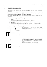
Page 268: ...ero return position machine zero point This is indicated in the program in the following manner 1 G00 T_ The coordinate system is set using the tool geometry offset function 2 G54 G59 The coordinate s...

Page 269: ...position of the cutting tool mounted in the turret in these coordinate systems in the NC Because a diametral command is used for the X axis the value to be set is twice the actual distance Positive Di...

Page 270: ...oordinate system for headstock 2 X0 Spindle center Z0 Left end face of the workpiece Coordinate system plus minus sign X axis For the X axis reversed JIS specification machine positive and negative di...

Page 271: ...andard tool selection appropriate 4 Is the measured dimension correct 5 Is the calculation for offset data correct 6 Is the offset direction correct 7 Is the tool offset number correct 8 Are the tool...

Page 272: ...TING MASS PRODUCTION This chapter explains the procedures for checking a program and finishing a workpiece within the specified tolerance before starting mass production The checkups before starting m...

Page 273: ...unction E 13 6 2 Checking a Program by Using the Spindle OFF Mode Function E 14 7 CHECKING THE PROGRAM WITH A WORKPIECE CLAMPED IN THE CHUCK E 18 8 TO FINISH A WORKPIECE WITHIN THE SPECIFIED TOLERANCE...

Page 274: ...he machine are free of program error and machine error The status indicator ERR is not lit 6 The turret is indexed to the correct position The status indicator TRCL is lit 7 If the spindle is rotating...

Page 275: ...utomatic operation in the memory mode including feed hold state the start interlock becomes enabled This interlock function prevents restarting of automatic operation with modal information such as of...

Page 276: ...achining conditions such as the chucking pressure spindle speed feedrate and depth of cut Periodically measure the chuck gripping force with a gripping force meter to make sure that the required gripp...

Page 277: ...cking method correct 9 Is the progress of cutting been observed 10 Are coolant supply volume and direction correct 11 Are the cutting tools free of interference with the workpiece jaws and chuck 12 Ar...

Page 278: ...s used to check the program turned off 2 Is dimensional variation checked 3 Are run out on I D and O D and end face waviness measured 4 Is a target work time established on the basis of the machining...

Page 279: ...pected manner and the spindle could be rotated at an unexpected speed leading to accidents involving serious injuries or damage to the machine Check the interlock setting Check Items Check Column 1 Ch...

Page 280: ...mn 1 Chuck clamp CHCL Lit 2 Turret index completion TRCL Lit 3 Machine ready MRDY Lit 4 Zero return completed X Z Lit Check the tool offset data Record the work shift data before ending operation for...

Page 281: ...etc It is necessary to shape the soft jaws so that the workpiece can be clamped in the chuck stably Chapter C SHAPING SOFT JAWS FOR FINISHING 2 Mount the tools and the workpiece in the machine by movi...

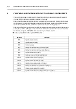
Page 282: ...rocedure explained in 4 1 Preparations for Checking a Program 2 Place the DOOR INTERLOCK key switch in the NORMAL position 3 Close the front door 4 Place the PANEL key switch in the ON position 5 Carr...

Page 283: ...screen 14 Search for the program 15 With the manual door type machine press the DOOR UNLOCK switch to unlock the front door Then open the front door With the automatic door type machine open the front...

Page 284: ...rder Spindle speed 3 If the coolant OFF mode is currently valid coolant will not be supplied even if an M08 coolant ON command in the program is carried out WARNING Before switching the machine lock f...

Page 285: ...e following M code commands are not executed in automatic operation Although axis movement commands are executed the axes are moved at the feedrate set by the OVERRIDE dial since the dry run function...

Page 286: ...hat jogging the spindle and the rotary tool spindle M type is allowed 5 When the spindle OFF mode function is valid coolant is supplied when the CLTON switch is pressed 6 When the spindle OFF mode fun...

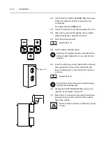
Page 287: ...displaying the OPERATION PANEL screen and place the chuck in the clamped state Page A 31 5 6 12 Make the dry run function invalid and coolant off mode valid if considered necessary for the program te...

Page 288: ...rn the indicator in the switch off For programs in which the cutting feedrate is expressed as the amount of feed per revolution of the spindle a program check is not possible even if the dry run funct...

Page 289: ...he clearance between the cutting tool and the chuck in comparison with the data for DIST TO GO which is displayed on the screen If there is a possibility of interference between the tool and the chuck...

Page 290: ...xis or index the turret return the axis or the turret to the previous position before restarting the no load running of the program If the no load running is restarted after indexing other tool or wit...

Page 291: ...n the program Allowance on end face 1 When 100 0 is added to COMMON Z with the headstock 2 specification machines the spindle 2 side is also shifted 100 0 in the plus Z axis direction causing possible...

Page 292: ...heck if necessary 5 After finishing the program check always reset the shift amount to its original value The procedure to check the program by shifting the coordinate system 100 mm in the Z axis dire...

Page 293: ...that the rapid traverse rate override feedrate override and spindle override are set correctly 13 If there is an M08 coolant ON command in the program press the CLTOFF switch for 1 second or more to m...

Page 294: ...if an M08 coolant ON command in the program is carried out 21 Check the clearance between the cutting tool and the chuck in comparison with the data for DIST TO GO which is displayed on the screen If...

Page 295: ...hout returning to the previous position a tool may strike the chuck or other problems may occur causing damage to the machine 25 If the measured clearance is appropriate and there is no possibility of...

Page 296: ...t workpiece in test cutting exercise due care to ensure safety Offset in the Z axis direction is impossible for thread cutting or grooving 1 Carry out the procedure explained in 4 1 Preparations for C...

Page 297: ...ut 0 3 using the data entry keys e Press the INPUT soft key Do not input the offset data in the radial direction for tools such as centering drills and drills for cutting at the center of a workpiece...

Page 298: ...door type machine when the program stops after executing the M01 optional stop command open the front door by pressing the AUTOMATIC DOOR OPEN switch 2 The machine does not stop if an M01 command is...

Page 299: ...chined 0 35 mm larger than the programmed diameter the offset data should be input to machine the workpiece 0 35 mm smaller Input 0 35 using the data entry keys d Press the INPUT soft key 1 If the INP...

Page 300: ...r obtaining the tool wear offset data precisely for all the tools Before starting automatic operation a Invalidate the single block function b Invalidate the optional stop function c Invalidate the co...

Page 301: ...ibit the entry of a cutting tool into the zone defined using the stored stroke limit function If the cutting tool is going to be moved in the zone the related alarm message is displayed on the screen...

Page 302: ...hining make sure that the workpiece is supported not to fall from the chuck if the tailstock spindle center retracts from the workpiece WARNING 1 Always stop the machine before removing chips inside i...

Page 303: ...before restarting the program If the program is restarted from a position different from the previously located position an interference will occur between the tool and the workpiece or between the t...

Page 304: ...tor CHCL is lit Check the workpiece to see if it is correctly clamped in the chuck 5 Close the front door 6 Display the PROGRAM memory screen and make sure that the cursor is at the head of the progra...

Page 305: ...9 Display the PROGRAM memory screen and make sure that the cursor is at the head of the program 10 Check the setting of the switches mode selection switches OVERRIDE dial etc 11 Close the front door 1...

Page 306: ...le is in the OUT state At the same time the program must be written by using these interlock functions fully and with operation safety taken into consideration For interlock functions refer to page A...

Page 307: ...OPE PANEL When the block delete BDT function is selected The block delete function becomes valid when the M89 command is read as many times as the number set for the work counter If the START switch...

Page 308: ...nd press the E key 1 The numeric keys 1 to 6 correspond to respective digits of the display Each time a numeric key is pressed the corresponding digit is incremented by one 2 If the numeric key is pre...

Page 309: ...umber of machined workpieces with a built in battery Each time the M89 command in the program is read the total counter is incremented 1 The average service life of the battery is seven years 2 The ba...

Page 310: ...ol Presetter OUT IN Switches TOOL PRESETTER OUT IN Option A 51 Automatic Operation Switches CYCLE A 22 Automatic Power Shutoff Switch AUTOMATIC POWER SHUTOFF Option A 51 Auxiliary Function Lock A 30 A...

Page 311: ...ck Clamp Direction A 28 Chuck Clamp Unclamp Operation B 32 Chuck Footswitch A 31 CHUCK JAW STROKE END DETECTION FUNCTION C 25 Chuck Jaw Stroke End Detection Switch A 31 Chuck Opening Closing Footswitc...

Page 312: ...B 8 Emergency Stop and Door Unlock Automatic Door Type P 29 Emergency Stop and Door Unlock Manual Door Type P 25 Emergency Stop Button EMERGENCY STOP B 9 Emergency Stop Button EMERGENCY STOP A 12 F Fe...

Page 313: ...54 Lock and Unlock of Automatic Door P 26 Lock and Unlock of Manual Door P 23 M Machine Light Switch LIGHT A 48 Machine Lock A 30 Main Switch A 9 Manual Lubrication Pushbutton A 55 MANUAL OPERATION OF...

Page 314: ...Opening Closing the Door Automatic Door Type P 27 OPERATION PANEL A 14 Operation Panel Screen A 57 OPERATION PROCEDURE FOR DIFFERENT TYPES OF MACHINING E 31 Optional Stop Switch OSP A 25 P Panel Key...

Page 315: ...ower Area of the Operation Panel A 13 S SAFETY GUIDELINES B 1 SAFETY PRECAUTIONS A 1 SELECTING TURRET B 15 Setting the I O destination I O channel A 58 SETTING THE INHIBITED TOOL ENTRY ZONE E 28 Shapi...

Page 316: ...he Tailstock Clamp Unclamp Switches TSCLP TSUCLP Servo controlled Tailstock Specification A 53 TO FINISH A WORKPIECE WITHIN THE SPECIFIED TOLERANCE WITH THE TOOL WEAR OFFSET FUNCTION TEST CUTTING E 23...

Page 317: ...DOOR OPEN CLOSE DOOR INTERLOCK FUNCTION switch P 27 Automatic Door Open Close Switch AUTOMATIC DOOR OPEN CLOSE Automatic Door Specification A 52 Automatic In Machine Tool Presetter OUT IN Switches TOO...

Page 318: ...tch A 35 Chucking Pressure Adjustment Handle A 55 CL Spindle Clamp Switch M Type A 50 CLTOFF Coolant Off Switch A 47 CLTON Coolant On Switch A 47 Coolant Switches A 47 CYCLE Automatic Operation Switch...

Page 319: ...P 7 J JOG Jog Feed A 21 L LIGHT Machine Light Switch A 48 Loader Valid Switch Loader Specification A 54 M Machine Light Switch LIGHT A 48 Machine Lock A 30 Main Switch A 9 Manual Lubrication Pushbutto...

Page 320: ...A 10 Power Supply Lamp POWER SUPPLY Option A 10 R Rapid Traverse Rate Override Switches A 43 Reset Key EMERGENCY STOP B 11 REV Spindle Reverse Rotation Switch A 38 RPD Rapid Traverse A 21 RS232C Inter...

Page 321: ...A 29 Tailstock Spindle Switches Tailstock Specification A 49 Tailstock Spindle Thrust Adjustment Handle Tailstock Specification A 56 TAPE Tape A 20 The Tailstock Clamp Unclamp Switches TSCLP TSUCLP Se...

Page 322: ...nob DOOR INTERLOCK FUNCTION P 8 W WARNING label DOOR INTERLOCK FUNCTION P 8 Work Counter A 29 X X Z Zero Return Indicator A 34 Y Y Status Indicators A 34 Z Zero Point Adjustment A 32 Zero Return Indic...

Page 323: ...t your comments to those concerning this manual only Comments can also be submitted using the company website at http www moriseiki com Name of Manual OPERATION MANUAL Number of Revisions OM NZSMSC700...

Page 324: ...Phone 39 02 4894921 Fax 39 02 48914448 MORI SEIKI ESPA A S A Head Office Technical Center Calle de la Electr nica Bloque B Nave 9 Poligono Industrial La Ferreria 08110 Montcada I Reixac Barcelona Spai...

Reviews: