background image

2-568

詳細説明

MACHINE OPERATIONS

29-15-3

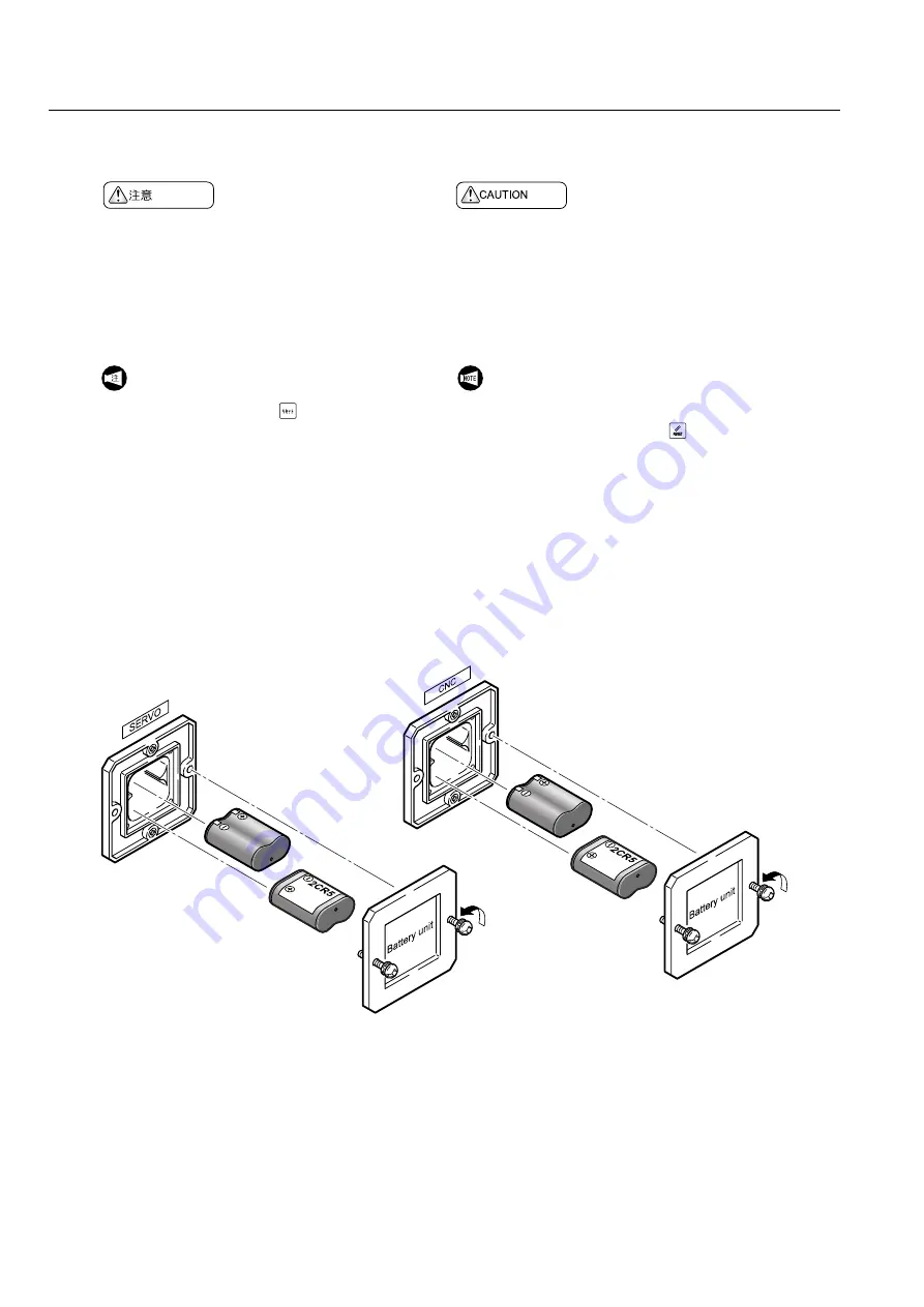
バッテリの交換

Replacing Batteries

<手順>

1)

機械電源を投入する。

2)

NC

電源を投入する。

3)

バッテリカバーを外す。

4)

新しいバッテリ(

FCU6-BTBOX

)と交換する。

5)

バッテリカバーを取り付ける。

<Procedure>

1)

Turn ON the main power.

2)

Turn ON the NC power.

3)

Remove the battery cover.

4)

Replace the old batteries with new ones (FCU6-

BTBOX).

5)

Remount the battery cover.

NC

電源投入状態でバッテリを交換してください。

NC

電源しゃ断状態でバッテリを交換すると、メモリ

内のデータおよび絶対位置が失われます。
データの消去を防ぐために、電池交換前にメモリ
カードなどの外部入出力機器を使って、パラメータ
やプログラムなどのメモリ内のデータを出力してく
ださい。パラメータやプログラムなどのメモリ内の
データが消えてしまっても弊社は責任を負いません。

Change batteries with power supplied to the NC.  If 

batteries are changed with the NC power supply turned 

OFF, the data stored in the memory and the absolute 

position are lost.
In order to avoid losing memory data such as 

parameters and programs, save to an external I/O 

device or a memory card.  Mori Seiki does not accept 

responsibility for the loss of memory data.

1.

バッテリが正しい向きで取り付けられて
いることを確認してください。

2.

バッテリ交換後、


(リセット)キーを

押してもアラームが消えない場合は、電
源を切らずに弊社サービス部門にご連絡
ください。

1.

Always ensure the polarity of the batteries is cor-

rect.

2.

If the alarm is not reset after the batteries have 
been replaced and the 


(RESET)

 key pressed, 

leave the power turned ON and contact Mori Seiki 

Service Department for assistance.

Summary of Contents for MSX-850

Page 1: ...eration maintenance or programming carefully read the manuals supplied by Mori Seiki the NC unit manufacturer and equipment manufacturers so that you fully understand the information they contain Keep...

Page 2: ...these points before using the machine Mori Seiki will not be liable for any damages occurring as a direct or indirect consequence of using the machine without clarifying these points All rights reserv...

Page 3: ...ure This machine is suitable for manual and automatic operation Tools This machine is capable of using common turning tools and rotary tools such as milling cutters drills and taps Contact Mori Seiki...

Page 4: ...to improvements to the machine All rights reserved reproduction of this instruction manual in any form is not permitted without the written consent of Mori Seiki The following manuals are supplied in...

Page 5: ...hich if not avoided will result in death or serious injury Indicates a potentially hazardous situation which if not avoided could result in death or serious injury Indicates a potentially hazardous si...

Page 6: ...6 4 P 10 Safety Practices during Setup 6 5 P 11 Automatic Operation 6 6 P 12 Interlock 6 7 P 12 Data 6 8 P 13 Precautions when Operating Special Specification Machines 7 NC P 14 NOTES CONCERNING NC P...

Page 7: ...rgency Stop with the RESET Key and Canceling the Emergency Stop Status 4 2 3 1 12 Press the Automatic Operation Button Feed Hold to Execute or Cancel an Emergency Stop 4 3 1 12 Turning OFF Power Suppl...

Page 8: ...1 34 Interlocks for Using the Manual In Machine Tool Presetter 10 1 36 TOOL GEOMETRY OFFSET VALUE MEASUREMENT ENTRY WITH MANUAL IN MACHINE TOOL PRESETTER 10 1 1 38 Measurement Procedure with the Manua...

Page 9: ...1 62 Digital Tailstock Setting 15 2 2 1 63 Selecting the Workpiece 15 2 3 1 63 Setting the Thrust Force and Re Chucking 15 2 4 1 64 Setting Retract Approach and Thrust Positions 15 2 5 1 65 Checking...

Page 10: ...amming 17 2 1 77 Axis Control and Direction 17 2 1 1 77 Movement along the Controlled Axes 17 2 2 1 79 Expressing Axis Movement in Programming 17 3 1 81 Specifying the Dimensions 17 4 1 82 Functions o...

Page 11: ...S PRODUCTION 21 1 1 111 Conditions for Starting Automatic Operation 21 2 1 113 Check Items before Starting Mass Production 21 3 1 114 Inspection Items at Beginning End of Daily Operation 21 3 1 1 114...

Page 12: ...and Stopping Spindle Rotary Tool Spindle Rotation 2 6 5 1 2 17 Starting Spindle Rotation Manually 2 6 5 2 2 17 Stopping Spindle Rotation 2 6 5 3 2 18 Starting the Rotary Tool Spindle Manually 2 6 5 4...

Page 13: ...ators 3 NC 2 32 NC OPERATION PANEL 3 1 2 32 Soft Keys 3 2 2 33 Page Selection Keys 3 3 2 33 Program Edit Keys 3 4 2 34 Key Input Buffer Area 3 5 2 34 Data Entry Keys 3 6 2 34 INPUT Key 3 7 2 34 RESET...

Page 14: ...er File Directory Screen 4 2 5 2 50 Program Restart Screen 4 3 2 51 Function Selection Key OFFSET 4 3 1 2 53 Tool Geometry Offset Screen 4 3 2 2 54 Tool Wear Offset Screen 4 3 3 2 55 Work Offset Scree...

Page 15: ...ction Selection Key MESSAGE 4 6 1 NC 2 63 NC Alarm Screen 4 6 2 PLC 2 63 PLC Alarm Screen 4 6 3 2 63 Alarm History Screen 4 6 4 2 63 Application Message Screen 4 7 2 64 Function Selection Key SETTING...

Page 16: ...5 3 2 78 Search Function 5 3 1 2 78 Program Number Search 5 3 2 2 78 Sequence Number Search 5 3 3 2 79 Word Search 5 4 2 80 Program Edit 5 4 1 2 81 Editing a Program by Word Unit 5 4 2 2 81 Editing a...

Page 17: ...C to the User Memory Area 7 G 2 94 G FUNCTIONS 7 1 G 2 94 G Code List 7 2 G00 2 99 G00 Positioning the Cutting Tool at a Rapid Traverse Rate 7 3 G01 2 101 G01 Moving the Cutting Tool along a Straight...

Page 18: ...1 I 2 153 Argument Assignment I 7 19 1 2 II 2 154 Argument Assignment II 7 19 1 3 2 154 Mixture of Argument Assignments I and II 7 19 2 2 155 Nesting Level for Calls 7 20 G66 G66 1 G67 2 156 G66 Macro...

Page 19: ...01 Optional Stop 9 3 M02 M30 2 195 M02 Program End M30 Program End and Rewind 9 4 M03 M203 2 M04 M204 2 M05 2 2 196 M03 Spindle Start M203 Spindle 2 Start M04 Spindle Start in the Reverse Direction M2...

Page 20: ...e 2 Break Unclamp 9 17 M70 M482 M483 2 215 M70 Bar Stock Supply ON M482 New Bar Stock Supply to Bar Feeder M483 Bar Stock Supply OFF Option 9 18 M73 M74 2 217 M73 Work Unloader OUT M74 Work Unloader I...

Page 21: ...of Tool Geometry Offset and Coordinate System 14 2 2 247 Preparation for Tool Geometry Offset Coordinate System Setting 14 3 2 249 Tool Geometry Offset Value Measurement Entry 14 4 2 254 Setting Work...

Page 22: ...ommended Example Programs Automatic Tool Nose Radius Offset 16 R 2 287 MANUAL TOOL NOSE RADIUS OFFSET 16 1 2 287 General 16 2 2 288 Offset for Taper Cutting and Chamfering 16 2 1 2 288 Offset Method 1...

Page 23: ...2 335 G73 Calls the Closed Loop Cutting Cycle 18 3 G71 G72 G73 2 339 Cautions ON Using the G71 G72 and G73 Cycles 18 4 G70 2 342 G70 Calls the Finishing Cycle 18 5 G74 G75 2 344 G74 Face Cut Off Groo...

Page 24: ...4 and G88 19 7 1 2 402 Dwell Command 19 7 2 2 403 Precautions on Using the Tapper 19 7 3 2 404 To Finish Tapping at Correct Depth in Blind Hole 20 2 407 EXAMPLE PROGRAM 20 1 2 408 Notching Polar Coord...

Page 25: ...nd 21 4 2 442 New Tool Selection Signal and Tool Life Expiration Signal 21 4 1 2 442 New Tool Selection Signal 21 4 2 2 442 Tool Life Expiration Signal 22 2 443 THE LOAD MONITORING FUNCTION 22 1 2 443...

Page 26: ...tering Type Steady Rest Bolt tightening type Option 24 3 1 2 457 Steady Rest Buttons on Machine Operation Panel 24 3 2 2 457 Moving the Steady Rest 25 2 458 WORKPIECE TRANSFER 25 1 M G 2 460 M Codes a...

Page 27: ...COUNTER OPTION 28 1 2 482 Work Counter Option 28 2 2 483 Total Counter Option 28 3 2 484 Multi Counter Option 28 3 1 KOHKAN BOY 2 484 KOHKAN BOY Manufactured by Chita MFG CO Ltd 28 3 1 1 2 485 Lamps a...

Page 28: ...2 506 Coolant Unit 29 9 1 2 506 Precautions when Selecting Coolant 29 9 2 2 507 Replenishing Coolant 29 9 3 2 508 Cleaning Coolant Tank and Filter Chip Conveyor Right Side Discharge Specifications 29...

Page 29: ...Used Standard Specifications 29 11 5 Y 2 541 Flow of Lubricant and Positions where Used Y Axis Specifications 29 11 6 NL1500 NL2000 NL2500 2 542 Lubrication System Diagram NL1500 NL2000 NL2500 29 11 7...

Page 30: ...Cleaning Electrical Cabinet Fan 29 15 3 2 568 Replacing Batteries 29 16 2 569 Chip Conveyor Option 29 16 1 2 569 Precautions when Using Chip Conveyor 29 16 2 2 570 Operating Chip Conveyor 29 16 3 2 57...

Page 31: ...r Removal 30 6 4 2 592 Lubricating Unit Relief Valve Disassembly Cleaning 30 6 5 2 593 Lubricating Unit Relief Valve Adjustment 30 6 6 2 594 Lubricating Unit Lubricant Leakage Check 30 7 2 595 Oil Tem...

Page 32: ...n 5 Determine the most appropriate settings 6 Do not change or modify the machine without prior con sultation with Mori Seiki Mori Seiki is not liable for acci dents 7 Take adequate safety measures fo...

Page 33: ...ate the machine with protective covers removed or while other safety devices are in invalid status 5 Do not put too much confidence in safety devices protective covers and doors Recognition of the dan...

Page 34: ...e caution labels attached to the machine are written in the native language of the operator 5 Contact the Mori Seiki Service Department on purchasing new caution labels and other inquiries Refer to MA...

Page 35: ...rs protective gear to avoid injury due to excessive noise levels Impaired hearing 4 Before operating the machine confirm there are no personnel or obstacles around or inside the machine Keep distance...

Page 36: ...ith a hollow chuck install the attached through hole cover to the chuck if the through hole is not used Chuck cylinder or other hydraulic circuit malfunction due to entry of coolant or chips 19 Contac...

Page 37: ...ne operation or immediately following power OFF Burns 5 Do not stop spindle rotation while a cutting tool is in contact with the workpiece Cutting tool and machine damage 6 When the turret head is rot...

Page 38: ...nd fixture ejection 4 If a workpiece holding chuck or fixture other than the chuck supplied with the machine is used contact the Mori Seiki Service Department prior to machine operation to prevent ser...

Page 39: ...etting the speed of the chuck by taking the workpiece dimensions and shapes cutting force and chuck maintenance and inspections into consideration Rotate the spindle at a speed no faster than allowabl...

Page 40: ...workpiece is not at the center of the rotation balance using a balancer with full consideration given to machining conditions such as the spindle speed Workpiece ejection 5 Do not rotate the spindle w...

Page 41: ...he lowest setting To Prevent Turret Head Indexing Set the Turret Indexing button to the station number currently indexed Turn the operation selection key switch to Operation Disable 2 When using a bar...

Page 42: ...e lock function from valid to invalid ensure change is performed after executing a cycle Gap generated between program command and machine position 6 Confirm the cycle start indicator is extinguished...

Page 43: ...tions must be ON when operating the machine If necessary to operate the machine with interlocks released awareness of the dangers involved and particular attention given to safety during machine opera...

Page 44: ...4 1 4 5 1 5 6 1 Industrial Robot Specifications Only qualified personnel trained and approved in accordance with local regulations may operate robots Unauthorized personnel may not operate robots unde...

Page 45: ...st and then the X axis to position the cutting tool at the approach point In the cutting tool retraction operation first retract the X axis to a point where continued cutting tool movement does not in...

Page 46: ...contain residual electrical energy Using a tester confirm parts are free of residual energy prior to per forming maintenance procedures Maintenance pro cedures undertaken with the power turned ON mus...

Page 47: ...n from machine Do not touch chips or tool cutting edges without wearing protective gloves Injury Mori Seiki does not accept responsibility for accidents arising from the use of non specified replaceme...

Page 48: ...enter Device SOUND LEVEL METER TYPE 1015 Japan Electronic Instrument Co LTD Frequency Characteristics A Nominal a weighting frequency characteristics Level Dynamic response Fast Default Value Backgrou...

Page 49: ...the spindle running and the axes traveling Model NL2000SY 500 Serial No NL201DB0009 Date 2004 12 29 Specifications Max spindle speed 5000 min 1 Rapid traverse rate X Z 30 m min Y 10 m min Measured by...

Page 50: ...axis 65 65 66 73 66 Y Y axis 63 63 64 69 65 Z Z axis 66 67 69 75 72 When Turret Turning T Turret operation 64 64 68 74 68 Model NL2000SY 500 Serial No NL201DB0009 Date 2004 12 29 1 1 1 m 1 55 0 75 m...

Page 51: ...LA 4350 Frequency Characteristics A Nominal a weighting frequency characteristics Level Dynamic response Fast Default Value Background noise 58 dB dB Emitted Sound Pressure Level 1 Measuring Point 1 A...

Page 52: ...min Y 10 m min Measured by TM Yoshioka Kiyoshi Department Quality Assurance Section Value Performance Name Yoshioka Kiyoshi Measured at Development testing center Device SOUND LEVEL METER TYPE 1015 J...

Page 53: ...ret operation 63 63 64 71 66 Model NL3000Y 1250 Serial No NL301DC0009 Date 2005 01 08 1 1 1 m 1 55 0 75 m 2 100 2 1 1 Measured 1 m away from the machine and at a height of 1 55 0 75 m from the floor 2...

Page 54: ...1 CHAPTER 1 BASIC OVERVIEW...

Page 55: ...NE TOOL PRESETTER page 1 36 SETTING WORKPIECE ZERO POINT Z0 page 1 44 Chuck 1 52 JAW SHAPING page 1 52 Chuck opening closing footswitch 1 48 CHUCKING page 1 48 2 Tool Presetter Arm Chuck Lubricating U...

Page 56: ...tailstock specifications 1 59 TAILSTOCK page 1 59 No Component Refer to 6 6 7 8 6 9 7 10 6 12 11 No Component Refer to Electrical cabinet 2 3 Electrical Cabinet Door page 2 3 Main power switch 1 9 2...

Page 57: ...2 1 10 100 100 0 150 B Y C Z X B B C Z C Z X X Y Y 200 100 0 3 1 2 50 NC C1 1 1 1 2 2 2 C2 100 MDI C C X Z C Y X Z C ATC HP B B Z X 2 27 2 8 2 6 NC 2 9 2 23 2 19 2 23 2 22 2 26 2 12 2 27 2 6 2 11 2 21...

Page 58: ...Conveyor Specification page 2 27 Automatic Operation Buttons page 2 8 Mode Selection Buttons page 2 6 NC Function Buttons page 2 9 Handle Switches page 2 23 Axis Feed Buttons page 2 19 Rapid Traverse...

Page 59: ...Explanation of NC Operation Panel keys can be found in NC OPERATION PANEL page 2 32 MACHINE OPERATIONS Refer to the page indi cated by the number with the key name 10 F 8 F 9 F 7 F 6 F 1 F 2 F 4 F 5...

Page 60: ...anual the operations by keys and but tons are indicated in the methods below Soft key NC operation panel key Buttons switches 2 Selecting automatic mode manual mode means pressing one of the buttons b...

Page 61: ...6 Setting of Workpiece Zero Point Z axis page 1 44 Checking Adjusting Chuck Pressure page 1 51 Completion of Jaw Shaping Installing Tools for Workpiece Cutting page 1 25 Tool Geometry Offset Data Sett...

Page 62: ...r 4 There are not any unreasonable demands in terms of lathe cutting accuracy 5 All the dimensions and listings in the diagrams have been checked 6 The cutting order and cutting conditions are appropr...

Page 63: ...itiated by the weekly timer 5 Pull out the Emergency Stop button 6 NC EMG Press the NC power button ON again ON Emergency stop state is reset EMG display disappears 7 Open the door then close the door...

Page 64: ...by pressing any of them State of the Machine All machine operation stops regardless of the operation mode manual or automatic The message EMG blinks on the screen MC Y When the Emergency Stop button o...

Page 65: ...PROG The PROGRAM memory screen is displayed 4 Press the REWIND soft key The cursor moves to the head of the program 5 Close the door 6 Carry out the zero return operation 1 EX4002 2 2 573 1 13 If the...

Page 66: ...MC Y specifications axis movement is stopped at the position where a single block stop is valid in the cycle b While a thread is being cut in cutting feed the machine stops after executing the first...

Page 67: ...ine Operation Panel page 1 3 for the locations of switches and buttons 1 Set the door interlock key switch in the NORMAL position 2 Close the door 3 Turn the operation selection key switch to Operatio...

Page 68: ...the door is open axes feed is performed by pressing and holding down the One Touch Zero Return button 1 2 3 X Z Y Y 1 2 3 4 0 1 Y Y X 2 X Z Y The axis order for zero returns can be set on the panel se...

Page 69: ...nable 4 Press the mode selection Zero Return button 5 C C1 C2 C C2 2 Press the C axis selection button C1 or C2 The C axis selection button C2 is for Headstock 2 specifications 6 C Press and hold down...

Page 70: ...key switch in the NORMAL position 2 Press the Door Unlock button 3 Open the door 4 Turn the operation selection key switch to Operation Enable or Operation Edit Enable 5 Press the mode selection butt...

Page 71: ...button extinguished 1 Press the Door Unlock button Button illuminated 2 Open the door Close and lock door Status Door open Door Unlock button illuminated Close the door Status Door closed but unlocke...

Page 72: ...terclockwise to unlock the door Door unlocked 1 20 DOOR INTERLOCK FUNCTION page 1 20 The operator door is automatically locked when closed and cannot be opened from the inside If setup cleaning inspec...

Page 73: ...inside using the follow ing procedure 1 Remove the rubber grommet at the door lock device mounting position inside the machine 2 Turn the door unlock lever on the under surface of the door lock devic...

Page 74: ...Label Status Indicator Door Interlock Key Switch Manual Return Type 1 2 NC 1 Note that releasing the door interlock function to enable limited machine operations with the door open is extremely dange...

Page 75: ...ion panel and turn the volume adjusting knob on the back of the WARNING label using a phillips head screwdriver Clockwise rotation Increases the volume Counterclockwise rotation Decreases the volume D...

Page 76: ...the tailstock Chuck clamping unclamping 2 M00 M01 M02 M30 M85 M86 M Automatic door 2 M code commands M00 M01 M02 M30 M85 M86 in automatic operation 2 M S T Automatic door 2 M codes S codes T codes and...

Page 77: ...t Collision Workpiece chip and coolant ejection Serious injury Releasing door interlock Turn the door interlock key switch to the RELEASE setting Status indicator INTERLOCK RELEASED flashes Buzzer act...

Page 78: ...tion Spindle or rotary tool spindle rotation 1 1 Spindle or rotary tool spindle inching 2 Turret indexing 3 Axis feeding Coolant supply Chip conveyor operation Tailstock advance return Chuck clamping...

Page 79: ...he turret head Entanglement Collision Serious injury 2 When loosening bolts on tool holders and cutting tools adopt a balanced stance and then loosen the bolts gradually Unexpected contact with machin...

Page 80: ...the turret number which precedes by 1 or 2 before the turret number on which the tool holder is to be mounted by pressing the Turret Station Setting button Number flashing 8 Press the Turret Indexing...

Page 81: ...position to match the tool holder mounting direction if necessary Mounting Turning Tool Holder Coolant Hole Alignment Coolant Supply Hole Plug Mounting Rotary Tool Holder Coolant Hole Alignment Coola...

Page 82: ...Turret head scratching Tool tilting Machining defects 4 Remove scratches on the turret head mounting sur face using an oil whetstone 5 Tighten bolts with a consistent tightening torque Sub standard m...

Page 83: ...Bolt Key M12 M12 Bolt M12 M12 Bolt 1 1 26 Execute Preparation for Mounting Tool page 1 26 2 Tighten the tool holder clamp bolt to loosely clamp the tool holder to the turret 3 Loosely tighten the ecc...

Page 84: ...gure 2 in procedure 3 Interference Machine damage 3 Before mounting or removing a rotary tool remove the rotary tool holder so that the rotary tool is mounted or removed outside the machine After moun...

Page 85: ...ng the turret head with cutting tools mounted exercise extreme caution to ensure tools do not interfere with machine components such as the Z axis protector See diagram 1 Interference Machine damage I...

Page 86: ...ing it from the machine or container 2 do not subject it to shock especially the sensor portion Sensor damage Presetter arm deformation 1 2 1 2 1 2 1 Keep the parts below free of chips dust and other...

Page 87: ...Make sure that the connecting parts of the presetter arm and the base are free of chips and foreign matter 5 Install the presetter arm on the base while aligning the packing of the base with the groov...

Page 88: ...ter moving down 1 installing 2 the presetter arm axis movement is precluded unless the Presetter Mode button is illuminated Even if the button is illuminated and therefore the axis can be moved the ra...

Page 89: ...n is not displayed even if the indicator in the Presetter Mode button is illuminated check the following items if they are satisfied The protective cover of the presetter arm is mounted to the base of...

Page 90: ...ct with the stylus by moving two axes simultaneously or if the sensor is turned on although no axis is moved the tool geometry offset data is not input 2 Do not clean the sensor using the coolant gun...

Page 91: ...X4917 TOOL DOESN T TOUCH ON THE SENSOR is displayed Release the alarm by pressing the RESET key before pressing the Presetter Mode button and press the axis feed button again 3 In uni directional axis...

Page 92: ...e turret station number on which the tool to be measured is mounted 1 13 ZERO RETURN OPERATION page 1 13 1 2 2 1 1 10 10 1 12 12 1 16 16 2 17 26 10 17 28 12 17 32 16 T 2 233 2 51 1 SPINDLE 2 SPINDLE W...

Page 93: ...ctional measurement X Z Measure and enter the tool geometry offset values for the X and Z axes by following the procedure given above 7 Next tool measurement 1 2 3 6 1 Prior to rotating the turret hea...

Page 94: ...on Numerical value to be input distance from spindle center line to the X axis zero point as a radius value 2 The axis position data after zero return may deviate from those value indicated on the axi...

Page 95: ...mation in this section is provided so that you can understand the concept of tool offset and is not intended to explain how to adjust machine accuracy by such operations as presetter adjustment and ze...

Page 96: ...or is turned on when the tool tip comes into contact with face A of the stylus No 2016X NC NC parameter B X Sets the X coordinate value as a radius value where the sensor is turned on when the tool ti...

Page 97: ...e zero point and face D of the stylus No 39002 NC NC parameter Sets the distance as a radius value between the machine zero point and the spindle center ZWP Z Z axis work shift data which is set when...

Page 98: ...tter Mode button is illuminated If the Presetter Measurement button is pressed in this state the work shift data cannot be set correctly If the program is executed while the input work shift data is i...

Page 99: ...on regardless of the spindle to be used for machining resulting in interference Interference of the tool tool holder or turret head with the workpiece chuck or fixture Machine damage 1 Set the door in...

Page 100: ...ve the tool only in the X axis direction not in the Z axis direction With a workpiece whose end face does not require cutting it is not necessary to move the tool in the X axis direction In this case...

Page 101: ...g allowance 20 1 Z 2 3 1 G54 2 G55 2 mm G54 2 0 G55 2 0 Perform the following procedure to input the cutting allowance 1 Confirm that the cursor is positioned at the Z column of the selected work coor...

Page 102: ...pped by the workpiece soft jaws or tailstock if installed Injury 4 Set the chucking pressure within the permissible pressure range of either the cylinder thrust force or the chuck and cylinder pressur...

Page 103: ...tswitch pedal to be depressed 1 2 Footswitches are provided for both the spindle 1 and spindle 2 chucks Use the footswitch for the chuck to be operated Clamping chuck Step on the footswitch and push t...

Page 104: ...Fixing Footswitch Holes are provided on the footswitch to fix the footswitch to the machine Clamping chuck While pushing the lock release plate of the left footswitch forward step on the footswitch p...

Page 105: ...ssure adjustment handle lock nut to the left to loosen 2 While reading the pressure gage adjust the chucking pressure by rotating the chucking pressure adjustment handle 3 2 3 Using the footswitch ope...

Page 106: ...by the chuck manufacturer to mount the chuck jaws and tighten them securely Check at regular intervals to ensure the bolts are securely tightened 8 Do not use jaws excessively heavier than standard on...

Page 107: ...tting tools replaceable tool tip spindle speed and feedrate are all correct for shaping soft jaws 8 The workpiece contact face area is appropriate 9 Relief is provided at the soft jaw corners 9 19 Whe...

Page 108: ...tton and then open the door 12 Confirm that there will be no interference between the chuck or workpiece and the adjacent tools or fixture 13 Close the door 14 Start the spindle manually and adjust th...

Page 109: ...ol geometry and work offset data for the inner diameter cutting tool 1 6S 2 3 4 When chucking the plug for shaping the jaws exercise due care to avoid getting your fingers pinched 1 The accuracy of th...

Page 110: ...o the lowest setting and rotate the spindle in manual operation 3 Gradually increase the spindle speed to the maximum specified in the program Before shaping the soft jaws set the tool geometry offset...

Page 111: ...l default setting No 802 1 Reverse 3 The feedrate of cutting a relief can be set by MAPPS parameter No 1726 No 1726 0 50 of the finishing feedrate default setting No 1726 1 to 100 1 to 100 of the fini...

Page 112: ...lue 3 Press the RESET key Cursor moves to the top of the program 11 Press the mode selection button Memory 12 Press the automatic operation button Cycle Start Soft jaw shaping cycle starts 1 2 1 When...

Page 113: ...ement Entanglement Serious injury 2 An extraction bar used when removing the center from the tailstock body is fitted inside the tailstock on some models Do not operate the machine without the bar att...

Page 114: ...lstock Press the tailstock spindle 2 buttons Advance or Return to move the tailstock Programmable Tailstock 6 Set the tailstock interlock to ON 7 Remove the cover 8 Clean the tapered hole in the tails...

Page 115: ...e supporting the center by hand so that it will not drop Figure e 9 Remove the center from the front of the tailstock Figure f 1 62 1 69 2 64 For how to set the retract position refer to Digital Tails...

Page 116: ...ck key switch is returned to the NORMAL position Entanglement Workpiece chip and coolant ejection Serious injury 1 20 DOOR INTERLOCK FUNCTION page 1 20 1 63 1 63 1 64 1 64 1 64 1 65 Select the workpie...

Page 117: ...3000 1 07 to 9 80 kN 1 Return the door interlock key switch to the NORMAL position 2 Turn the operation selection key switch to Operation Edit Enable 3 Display the TAILSTOCK screen Function selection...

Page 118: ...al pulse generator observing the clearance between the workpiece and the tailstock through the machining chamber observation window 9 Press the TEACHING soft key 10 Move the cursor to APPROACH POSITIO...

Page 119: ...inated tailstock spindle 2 button Clamp lamp means that the tailstock is in the power down state CL The distance between the machine zero point and each position can be obtained by referring to the dr...

Page 120: ...he Digital Tailstock by Programming 1 2 2 2 28 2 1 72 1 Refer to Tailstock Spindle 2 Buttons page 2 28 for details on the tailstock spindle 2 buttons 2 Refer to Tailstock Spindle IN OUT Footswitches O...

Page 121: ...just tailstock positioning to ensure the work is securely held by the center when the spindle center is extended Following this adjustment secure the tailstock to the bed Workpiece ejection 1 20 DOOR...

Page 122: ...2 2 28 Refer to Tailstock Spindle 2 Buttons page 2 28 for details on the tailstock spindle 2 buttons 2 2 2 28 1 2 3 4 2 Refer to Tailstock Spindle 2 Buttons page 2 28 for details on the tailstock spi...

Page 123: ...hine elements will not interfere with the tailstock Interference of turret and tailstock Machine damage 1 Set the door interlock key switch in the NORMAL position 2 Close the door 3 Turn the operation...

Page 124: ...ator in the tailstock spindle 2 button Clamp blinks 6 Z Z Z 2 Press the axis feed button Z or Z selecting the direction that will connect the turret and tailstock and move the Z axis at the jog feedra...

Page 125: ...the door interlock key switch in the NORMAL position 2 Close the door 3 Turn the operation selection key switch to Operation Enable 4 Select the manual mode 5 Z Using Z axis travel move the turret in...

Page 126: ...he thrust for pushing the workpiece can be set and checked on the TAILSTOCK screen The indicator in the tailstock spindle 2 button Advance is illuminated In 2 Stepping on the tailstock spindle IN foot...

Page 127: ...with the chuck 4 Tighten the two hexagon socket set screws A again 5 Check that the bucket roller is aligned along the guide of the exit cover 6 Check that the bucket does not interfere with the exit...

Page 128: ...ly checked program in order to prevent the machine operator from misreading or inputting incorrect values Component interference Erroneous operation Workpiece ejection 5 Do not forget to enter decimal...

Page 129: ...iform cutting allowance Workpiece ejection 2 Contact Mori Seiki Service Department for assis tance when machining workpieces such as carbons and ceramics which disperse powder type chips during the ma...

Page 130: ...of five digits or less 1 to 99999 following the letter N Part Program A group of program which contains all the infor mation necessary for executing the cutting pro cess to be carried out by a single...

Page 131: ...direction The direction in which the machining diameter increases Z Turret direction The direction in which a cutting tool moves away from the spindle C MC Y C MC type Y axis specification Spindle di...

Page 132: ...in which the right hand thread advances when viewing a cutting tool from the spindle 1 2 Spindle 2 2 direction The rotation direction in which the right hand thread advances when viewing a cutting to...

Page 133: ...ct Z Z axis Z Z0 The longitudinal dimensions of a product are expressed using address Z Z0 is taken on the end face of the finished product C MC Y C axis MC type Y axis specification C C0 Spindle inde...

Page 134: ...o Point X0 Z0 X X Direction Tailstock X Z X Z X Z X Z X Z X Z X Z X X Direction X Z Turret Chuck Work Center Work X Y X Y X Y X Y Y Y Direction Y Y Direction X X Direction X X Direction X0 Y0 Workpiec...

Page 135: ...itions of tool and spindle 1 2 1 X_ W_ U_ Z_ X_ V_ 3 X 10 0 X10 0 4 X U Z W Y V C H 1 X10 0 U 20 0 U 20 0 5 Y Y Y_ V_ 6 MC Y C C_ H_ 1 X U 2 2 B B_ B 1 Generally a program is written using absolute co...

Page 136: ...ing coolant discharge ON OFF Example M08 Coolant discharge ON M09 Coolant discharge OFF 2 186 T T0101 1 1 T Function Specifies the tool number and the tool offset number Example T0101 Calls the No 1 t...

Page 137: ...ogramming This step may be omitted if the workpiece is simple 3 Study the cutting allowance Draw the blank workpiece if necessary 4 Determine the tools to be used Creating the tooling sheet 5 Determin...

Page 138: ...S screen 3 Using the MORI APL option MORI APL allows you to create programs automatically by entering the requested data in response to on screen instructions on a PC 17 5 3 Basic Pattern of Program 1...

Page 139: ...G00 X_ Z20 0 M08 Approach to the workpiece at a rapid traverse Starts coolant discharge G01 X_ Z_ F_ Approach to the workpiece at a cutting feedrate to ensure safety Machining program G00 U1 0 Z20 0 M...

Page 140: ...cifies the spindle speed 150 min 1 and the direction of rotation M03 Normal M04 Reverse Z_ M08 Z Approach to the workpiece Z axis direction Starts coolant discharge X_ X Approach to the workpiece X ax...

Page 141: ...mand in the program after completion of the program starting the auto matic operation is prevented even if the automatic operation button Cycle Start is pressed by mistake This is due to the tailstock...

Page 142: ...by mistake the cycle start or the spindle rotation will not be enabled due to the chuck interlock function If a hydraulic chuck is not used the internal signal is set to the chuck unclamp state so tha...

Page 143: ...r b Supporting the workpiece c Pressing the tailstock spindle 2 button Return to retract the tailstock spindle into the tailstock body d Removing the workpiece Chuck Tailstock Spindle Workpiece Chuck...

Page 144: ...containing a decimal point and symbols and are used In addition the symbol is also used for the block delete function Note that symbol cannot be used Block delete function If the block delete function...

Page 145: ...not entered it is assumed that the value is specified in the unit of least input incre ment inch setting specified by G20 X1 0 X1 inch X1 X0 0001 inch If a decimal point is not entered it is assumed t...

Page 146: ...om to the code entry must be X90 0 Z 5 0 F2 0 If you forget to use the dec imal point and enter X90 the machining path will be as indi cated by the thick line This happens because if there is no decim...

Page 147: ...ls for rotation in the clockwise CW direction 3 In the automatic tool nose R offset function G41 G42 the offset direction is reversed and command position of the imaginary tool nose differs Offset Dir...

Page 148: ...0 Z 35 0 X90 0 G03 X100 0 Z 40 0 R5 0 G40 G00 U1 0 Z20 0 X150 0 Z100 0 M09 M01 O1 G50 S2000 G00 T0101 G96 S180 M03 G41 X 50 0 Z20 0 M08 G01 Z2 0 F1 0 Z 30 0 F0 2 X 60 0 Z 35 0 X 90 0 G02 X 100 0 Z 40...

Page 149: ...nose radius offset data refer to AUTOMATIC TOOL NOSE RADIUS OFFSET page 2 256 For pocket cutting or contouring with an end mill set a cutter radius offset For details on setting the cutter radius off...

Page 150: ...function of the chuck or cylinder or a centrifugal force during high speed spindle rotation If machining is per formed without securing a sufficient gripping force the workpiece may fly out causing s...

Page 151: ...ation and coolant start MC Manual rotation of spindle and rotary tool spindle MC specifications MC Manual spindle and rotary tool spindle MC specifications jog speed operation is possible Automatic op...

Page 152: ...ss the mode selection button Jog 6 Rotate the turret head manually to return to the original position Status indicator lamp TRCL illuminated c Obtain tool geometry offset data Status Operation Remarks...

Page 153: ...th the workpiece jaws and chuck 9 The turret head is indexed at a position where there is no interference with the workpiece 10 The machine can be stopped immediately when necessary 11 The door is clo...

Page 154: ...chining on the screen Program number O No SEARCH 6 Execute program check 1 2 3 1 Press the automatic operation buttons Cycle Start and Feed Hold alternately and check the turret motion and the data di...

Page 155: ...button Cycle Start Program check restarts 3 When reaching the end of the program push the Program Check button Lamp extinguished Program check function invalid Procedure Repeat this confirmation proc...

Page 156: ...d turret and the tailstock 1 Take the workpiece shape and chucking method into consideration 2 When shifting the coordinate system determine the appropriate amount of shift 1 X 2 Z 2 2 1 Depending on...

Page 157: ...rate override and spindle override are set correctly 2 If there is an M08 coolant ON command in the program press the coolant button OFF for 1 second or longer The coolant button ON and Through spindl...

Page 158: ...yed on the screen through the machining chamber observation window 3 After the completion of the first axis movement block select any of the manual modes Spindle stop Procedure 1 1 X Z 2 M08 Confirm t...

Page 159: ...mpletion of the program a Display the WORK OFFSET screen b Move the cursor to COMMON Z using the cursor control keys c Input 100 0 using the data entry keys 2 Press the INPUT soft key Procedure Measur...

Page 160: ...tting Confirm the following points prior to performing a test cutting Check Items 1 The chucking pressure is checked and adjusted 2 If performing center work the tailstock spindle thrust is checked an...

Page 161: ...is functioning correctly 2 The choice of measuring instrument is correct 3 The measuring order is correct 4 The measuring method is appropriate 5 The area to be measured is indicated clearly 6 The ar...

Page 162: ...ting by shifting 0 3 mm in the radius direction a Using the cursor control keys align the cursor with the X axis data for the wear offset number for each tool b For tools used for O D cutting enlarge...

Page 163: ...you can press the Emergency Stop button or the automatic operation button Feed Hold immediately in a case that abnormality occurs 1 M01 2 M01 3 4 M01 M01 Proceed machining by observing vibration of t...

Page 164: ...program 1 2 3 4 1 Push the mode selection button Memory 2 Display the PROGRAM CHECK screen 3 Press the REWIND soft key 4 Confirm the cursor is at the head of the program 8 Restart cutting 1 2 1 Close...

Page 165: ...n automatic operation is temporarily suspended 1 8 External start interlock signal the signal which disables spindle rotation is not input 9 All axes have been returned to the zero point after the mac...

Page 166: ...ween the tool and the workpiece If an attempt is made to run a program in the memory mode with the start interlock function enabled the message EX5004 CHECK PROGRAM START POSITION is displayed and the...

Page 167: ...k thrust force When securing the workpiece using the tailstock Check the override switch settings 1 2 3 Are values for the following appropriate 1 Rapid traverse rate override 2 Feedrate override 3 Sp...

Page 168: ...operation 1 Cleaning 1 2 3 4 1 Cleaning slideway ball screw protective covers 2 Cleaning cylinder rear section Hollow chuck specifications 3 Cleaning chuck 4 Cleaning chip conveyor 2 Checking and adj...

Page 169: ...side to ensure that the workpiece is caught in the work unloader 3 After adjusting the workpiece ejector push the knob rightward to its original position Pressure Increased Pressure Decreased Adjusti...

Page 170: ...2 CHAPTER 2 MACHINE OPERATIONS...

Page 171: ...power supply cord for an external I O device Emergency Stop Button NC NC Power Buttons ON OFF Memory Card Interface RS232C RS232C Interface Connector AC100 V 100 VAC Electrical Outlet Emergency Stop B...

Page 172: ...a CF card 512 MB CF card E77029 512 MB CF card with an adapter MAPPSFIN0102171 1 GB CF card E77072 1 GB CF card with an adapter MAPPSFIN0108221 1 USB 256M USB E77120A01 512M USB E77121A01 1G USB E771...

Page 173: ...e OPEN RESET setting 5 Open the electrical cabinet door Electrical Cabinet Door Interlock Key Switch Main Power Switch Electrical Cabinet Doorlock 1 9 TURNING ON OFF POWER page 1 9 OPEN RESET The elec...

Page 174: ...the handle back to the ON setting 1 OFF 2 3 How to Lock the Main Power Switch Lock the main power switch using the following procedure when performing maintenance procedures considered dan gerous if t...

Page 175: ...trical cabinet door interlock key switch to the OFF setting In this condition the power supply can be turned ON even while the electrical cabinet door is open Ensure the main power supply is turned OF...

Page 176: ...e edited The key can be removed when the operation selection key switch is placed in this position Operation of the buttons and switches on the machine operation panel is possible In addition programs...

Page 177: ...teps in the range of 0 to 5000 mm min In the zero return mode an axis is manually returned to the zero point When carrying out one touch zero return operation it is necessary to select the zero return...

Page 178: ...matic operation are satisfied Unexpected machine start 1 2 G32 G32 3 G92 X Z 4 M MC 1 If the automatic operation button Feed Hold is pressed during automatic operation the spindle keeps rotating while...

Page 179: ...displayed on the screen This function is used to check the conditions of the cutting tool or to remove chips from the machine during automatic operation and to check a program at each process of test...

Page 180: ...PST Z 1 44 SETTING WORKPIECE ZERO POINT Z0 page 1 44 DRN 1 MC 2 Do not wake dry run function valid while in automatic operation Unexpected cutting feed rate 1 For the machines equipped with the pro gr...

Page 181: ...the buffer register To stop the process currently being executed in order to execute another process in this condition i e with the data for the next block stored in the buffer register clear the data...

Page 182: ...ng the spindle carefully check the workpiece chucking conditions the chucking pressure and the spindle speed Workpiece ejection 2 Be aware that the spindle will start rotating if the spindle rotation...

Page 183: ...indle to be operated These buttons are used to clamp unclamp the spindle C These buttons are used to select the C axis to be operated 1 2 1 SPINDLE 2 SPINDLE 1 2 1 MILLING 2 MILLING 1 2 1 SPCL 2 SPCL...

Page 184: ...indle Reverse direction Counterclockwise direction viewing a workpiece from the spindle This button is used to stop the spindle The spindle rotates while the button is pressed 1 2 NOR REV 1 The spindl...

Page 185: ...he spindle speed continuously in 2 decrements Pressing the spindle rotation button Stop simultaneously with this switch sets the spindle speed to 1 In the Automatic Mode 1 Spindle speed setting button...

Page 186: ...6 5 Starting and Stopping Spindle Rotary Tool Spindle Rotation 100 100 Override Before starting the spindle rotary tool in manual operation set the lowest available spindle speed using the spindle sp...

Page 187: ...operation modes 7 Set the spindle speed to the minimum value 1 by pressing the spindle speed setting button Decrease and the spindle rotation button Stop at the same time 8 Close the door 9 Start the...

Page 188: ...CL illuminated 8 Set the spindle speed to the minimum value 1 of the maximum spindle speed by pressing the spindle speed setting button Decrease and the spindle rotation button Stop at the same time 9...

Page 189: ...OPERATION page 1 13 TAILSTOCK 2nd SPINDLE B B C Z C Z X X Y Y RPD ONE TCH ZRN Before starting axis feed operation ensure that no one is near the moving parts and that you are moving the axis in the co...

Page 190: ...ation Enable or Operation Edit Enable 4 Press the mode selection button Jog 5 Set the feedrate to be used with the feedrate override switch 6 Press and hold down the axis feed button for the axis to b...

Page 191: ...Return Button This button is used to return all axes to the zero points through one touch operation When this button is pressed all axes return to the zero points in the order set on the screen 1 C C...

Page 192: ...elationship between the feedrate override switch setting and actual feedrate is indicated below 100 0 150 200 50 OVERRIDE 100 0 150 200 50 0 0 mm min Do not stop axis feed by setting the feedrate over...

Page 193: ...are used to carry out handle feed opera tions 2 73 1 100 50 2 100 0 3 1 2 1 2 3 Switch operation is impossible with the operation selection key switch placed in the Operation Disable The values in ar...

Page 194: ...axis is displayed to the left of the axis selection switch 5 Turn the manual pulse generator in the direction in which the selected axis is to be fed Setting X Z X Z Axis C M MC C Axis M MC Specificat...

Page 195: ...lected 4 The status indicator MRDY is illuminated 5 Turret head indexing has been completed normally The status indicator TRCL is illuminated 6 The machine is not in the reset state 7 There is no turr...

Page 196: ...id 2 13 Machine Light Button 2 14 Air Blow Button The Air Blow button is used to remove chips and foreign matter Air is supplied when this button is pressed APF TRIP OFF ON PC The main power switch is...

Page 197: ...on to release the door lock CHIP CONVEYOR STOP BACK FOR Do not attempt to reach inside the chip conveyor or put your feet in it while it is operating Entanglement Keep the chip conveyor operating duri...

Page 198: ...h Programmable tailstock NL3000 2000 3000 3000 Retracts the tailstock spindle into the tailstock 2 NL1500 2000 2500 3000 700 3000 1250 2 NL3000 2000 3000 3000 2 Tailstock Spindle 2 Button Inching Digi...

Page 199: ...ic mode Coolant ON OFF M08 Coolant supply starts when M08 coolant ON com mand is read Press the coolant button OFF to stop the coolant supply during automatic operation Coolant OFF mode 1 M08 Press an...

Page 200: ...ERR is illuminated or blinks if an alarm state is detected Status indicator ERR is illuminated A program error has occurred status indicator ERR blinks A machine error has occurred These status indica...

Page 201: ...ri Seiki Ser vice Department The status indicator CHCL1 is illuminated when the chuck is in the clamp state In this state spindle rotation is possible in both automatic and manual operations The statu...

Page 202: ...ion selection key and the soft keys F1 to F5 3 Menu selection key This key is used to display more menu options assigned to soft keys F1 to F5 if there are any 4 Menu selection key This key is used to...

Page 203: ...ds addresses and data In other words the key is used to replace an existing word with a new word 2 This key is used to insert a new word or block between two existing words It is also used to write a...

Page 204: ...cursor is displayed to indi cate the next data entry position 3 5 Data Entry Keys The data entry keys are the address keys and number keys used to input alphabetic and numeric characters 3 6 INPUT Ke...

Page 205: ...while the MAPPS parameter screen is dis played 3 10 CALC Key Pressing the CALC key will display a calculator on the screen Input values and perform calculations using the data entry keys After calcul...

Page 206: ...2 76 2 64 2 63 2 58 Function Selection Key PROG page 2 42 Function Selection Key POS page 2 40 Function Selection Key OFFSET page 2 51 Function Selection Key CAPS page 2 58 Function Selection Key NETW...

Page 207: ...s 1 2 1 Refer to the Loader Operation Manual for the screens displayed for loader operation 2 For description of the screens refer to the pages after the diagrams POS CURRENT POSITION ABS CURRENT POSI...

Page 208: ...GURATION CAPS OFFSET TOOL GEOMETRY OFFSET TOOL WEAR OFFSET WORK OFFSET SET UP TOOL MANAGE JAW TYPE MANAGEMENT SOFT JAW CUTTING CHUCK TAILSTOCK BARRIER SET TURRET INDEX POS TOOLING LIST TOOL LIFE MANAG...

Page 209: ...NUAL OPERATION COMMUNICATION PARAMETER SETTING SETTING MENU SET TIMER COUNTER F1 F1 DIGIT FEED SETTING PARAM CUSTMIZE FUNCTION SELECTION KEY NETWORK 2 Headstock 2 Specifications Tailstock Specificatio...

Page 210: ...a 4 1 3 Current Position All Screen The following position data is displayed on one screen Current position Relative and Absolute coordinate Position in the machine coordinate system MACHINE Remaining...

Page 211: ...ng the manual pulse generator when the optional handle interruption function is selected The axis movement distance value is cleared to 0 when an axis reaches the zero point 2 50 Function selection ke...

Page 212: ...gram screen etc The screen functions and soft keys dis played depend on the selected mode Mode Screen Reference Information Edit PROGRAM CHECK Foreground edit 1 96 PROGRAM LIST 2 48 BACKGROUND EDIT 2...

Page 213: ...2415 this func tion allows the Feed column of the PROGRAM CHECK screen to flash if a feedrate exceeding that value is specified with G98 or G99 during the memory tape or MDI operation To validate thi...

Page 214: ...lowing MAPPS parameters to display 2nd modal page and restart option 2nd modal page MAPPS parameter No 639 1 default setting 0 Restart option MAPPS parameter No 643 1 default setting 0 2 MAPPS No 650...

Page 215: ...ayed on the screen the soft key is used to select one of the programs CLOSE When two programs are being displayed the program that is selected for editing closes and the screen displays the remain ing...

Page 216: ...soft key is displayed in the second page of modal information 3 WORK 0 and RUN 0 are displayed when MAPPS parameter No 649 is set to 1 4 A total of 12 modal G codes are displayed in the first page of...

Page 217: ...he screen displays the load monitor information MAX 0 is displayed if MAPPS parameter No 651 is set to 1 1 2 2 2 72 1 The cursor is moved in the macro variable display area by pressing the cursor cont...

Page 218: ...y disabled is indicated in the STAT column In the edit mode or in background edit operation the screen is used for selecting the program to be edited In the memory mode it is used for selecting the pr...

Page 219: ...ed a Press OUTPUT SETTING CREATE FOLDER Enter a folder name EXECUTE b Move the cursor to the folder to be output c Press the INPUT key and SET d Specify a new file name if necessary When more than one...

Page 220: ...played to trans fer files to delete files and to change the connected host computer 4 2 5 Program Restart Screen When restarting a suspended operation from the desired block of a program if a tool is...

Page 221: ...n the TOOL GEOMETRY OFFSET screen The following parameter sets the valid or invalid status of the cursor follow up function MAPPS Parameter No 749 1 Valid Default No 749 0 Invalid With the default set...

Page 222: ...ts tool life management offsets fixture offsets and work offsets and condition settings is set in the MAPPS parameters MAPPS No MAPPS Parameter No Application Interlock Set on Shipping 746 Wear offset...

Page 223: ...changed data is reset to the previous data USED OFS MODE The tool geometry offset data of a program are collectively dis played Procedure CLEAR On pressing this soft key the data selected with the cu...

Page 224: ...sor position is cleared Default setting 1 ALL WEAR and ALL TOOLING soft keys are displayed to clear all the tool wear offset data C G18 2 183 C MAPPS No 2468 No 2468 5 F8 0 005 F9 0 005 NC Function se...

Page 225: ...ork offset data of a program is collectively displayed Procedure UNDO The previous value is reset Pressing the soft key moves the cursor to the changed data By pressing EXECUTE the changed data is res...

Page 226: ...posi tion is set as the turret index position 1 D MAPPS No 792 No 792 0 D No 792 1 D 2 MAPPS No 802 No 802 0 No 802 1 3 MAPPS No 1726 No 1726 0 50 No 1726 1 100 1 100 101 50 R 1 52 Function selection...

Page 227: ...f 100 mm Y Axis Stroke Restricted Specifications Option Y When using an O D rotary tool with a long overhang the Y axis stroke and the turret head rotation range are restricted by setting tool overhan...

Page 228: ...nput output of conversational programs and MAPPS parameters and the designation of macro variables is possible only to from a mem ory card or network option 2 In order to input data from or output dat...

Page 229: ...TPUT screen move the cursor to the data to be input 4 Press EXECUTE The selected data is input to the memory area 1 2 NC NC PC MAPPS MAPPS II PUNCH OUTPUT SETTING Move the cusor to the file or folder...

Page 230: ...displays the date Setting the Replacement Interval for the Machining Chamber Observation Window Move the cursor to MACHINING CHAMBER OBSERVATION WINDOW and press CHECK COMPLETE 2 488 PERIODIC MAINTEN...

Page 231: ...n 2 Types 4 and 5 are options 1 To change the details of a set inspection press COUNT STOP EXECUTE to stop the counter the edit the details For the editing procedure refer to Setting the Inspection Po...

Page 232: ...s used to make network settings Function selection key SYSTEM MACHINE STATUS Function selection key SYSTEM SYSTEM COMPOSIT MAPPS No 2 75 Function selection key SYSTEM MAPPS PARAM Input the parameter n...

Page 233: ...This screen displays alarms in order from the latest alarm Soft Key Function SEND MAIL MORI NET Global Edition Specifications By pressing the SEND MAIL soft key with the NC PLC ALARM screen or ALARM H...

Page 234: ...1 FOOT SWITCH VALID INVALID CHUCK 1 FOOT SWITCH AT DOOR CLOSE VALID INVALID CHUCK 1 STROKE END CONFIRMATION SWITCH VALID INVALID TAILSTOCK SPINDLE SWITCH VALID INVALID TAILSTOCK SPINDLE SWITCH AT DOOR...

Page 235: ...ommand is read as many times as the num ber set for the work counter the current program is continu ously executed to the end and then the machine stops When the Block Delete BDT Function is Selected...

Page 236: ...ed to set whether or not the chuck is opened closed when the footswitch is oper ated Valid The chuck is opened closed when the footswitch is operated Invalid The chuck is not opened closed when the fo...

Page 237: ...n of the tailstock spindle 2 button Return Tailstock Spindle Switch with the Door Close Tailstock Specifications If this function is set invalid tailstock spindle 2 buttons have no functions when the...

Page 238: ...apid traverse rate is clamped at fine feed When the present position is established after the adjustment of the zero point the setting for Zero Point Adjustment is automatically returned from valid to...

Page 239: ...er of the procedures below Select INVALID and then VALID of TURRET INDEXING FUNCTION VALID of TURRET INDEXING TEACHING is highlighted Select INVALID and then VALID of TURRET INDEXING FUNCTION VALID of...

Page 240: ...again If you fail to do so an alarm may occur 2 To restore the turret indexing acceleration decel eration data to the default setting on shipment select INVALID of TURRET INDEXING FUNCTION 3 During th...

Page 241: ...abled even while automatic operation is in progress paused or stopped 1 59 Function selection key SETTING SET TAILSTOCK Refer to TAILSTOCK page 1 59 Setting change Thrust change Workpiece change Opera...

Page 242: ...ons 1 4 1 7 This screen is used for Steady Rest Specification machines to set the hydraulic pressure connection to the steady rests to be used Setting Procedure Move the cursor to the selected steady...

Page 243: ...7513 1 000 1 mm NL1500 2000 230 000 NL2500 700 330 000 NL2500 1250 880 000 NC No 7513 2 1 16 2 25 Function selection key SETTING SET MANUAL OPE Move cursor to WORK UNLOADER OUT Work unloader is exten...

Page 244: ...data INPUT key The display item POWER ON displays the accumulated time that the power has been ON These value cannot be changed INPUT NC 1 20 1 2 3 1 17 Function selection key SETTING TIMER COUNTER P...

Page 245: ...d or invalid The selected item is highlighted 3 Press SET EXECUTE 4 Pressing the page selection key displays the second page of the communication parameters screen Function selection key SETTING PARAM...

Page 246: ...valid for the initially displayed screen selection function The options for the initially displayed screen are displayed 2 Move the cursor to INITIAL SCREEN and input the selection number displayed i...

Page 247: ...utions on Background Operation 1 2 3 1 Background editing is only possible for a program which is not used in the foreground operation 2 Alarms in the background occur in the same manner as during pro...

Page 248: ...fore the machine operates in a manner different from the program displayed on the screen O In the edit mode or if background editing is selected if the O No SEARCH soft key is pressed after inputting...

Page 249: ...earch and Program Bottom Search a Display the program on the screen and press REWIND or BOTTOM The program number or the last word is highlighted The cursor will be located on the first word of the pr...

Page 250: ...leted with the range selection operation move the cursor to any position after and cut the selected comment Note that or adjacent to O number can not be deleted or changed Example O4000 ABC EFGHI In A...

Page 251: ...Press SELECT b Select the range to be deleted and press CUT 2 Delete the data from the cursor position to a selected string a Input a string to delete to b Press the DELETE key EXECUTE 5 4 2 Editing...

Page 252: ...6 Press ALL or BELOW CURSOR or YES or NO for each occurrence of the specified word 5 4 5 Inserting Sequence Numbers Automatically MAPPS No 2404 1 32767 If 0 to 32767 is set for MAPPS parameter No 2404...

Page 253: ...a character other than N after the EOB code Example A character string in the key buffer area G92 X0 Y0 Z0 There is an EOB code at the end of the character string in the key buffer area and there is...

Page 254: ...ame and press EXECUTE Registering O Numbers in Groups 1 Select the group name ALL 2 Press CHANGE GROUP NM 3 Move the cursor onto the program to be registered 4 Press SELECT ON OFF 5 Repeat steps 3 and...

Page 255: ...xcerpt name 8 characters max 3 Press a soft key to allocate the entered excerpt name to it The excerpt name is displayed on the selected soft key Registering Excerpt Programs 1 Press REGIST PROGRAM 2...

Page 256: ...settings for I O device Once set the parameter settings may not be changed unless the external I O device is changed 5 5 2 Inputting Outputting a Program Cautions on Program Input Output Operation 1 2...

Page 257: ...lect a program Or press FOLDER select the folder and select a program to be input 8 Press SET 9 Press BG END In background operation only Alarm message INPUT ERROR 1 Another program is registered with...

Page 258: ...name 15 Press EXECUTE 16 Press BG END In background operation only 1 MAPPS No 669 No 669 0 1 No 669 1 O 2 MAPPS No 1610 1 TXT No 1610 0 No 1610 1 TXT O O 1 No 1610 0 2 TXT 1 The file output format ca...

Page 259: ...hen running DNC operation using a memory card the memory card is called the FRONT SIDE CARD M98 198 Sub Program Call M99 Return from Sub Program End page 2 224 O0001 M98 P0001 O0001 M99 NC USER MEMORY...

Page 260: ...e program to be executed using the cursor control keys and press FILE SEARCH or the INPUT key The selected file is displayed on the PROGRAM CHECK DNC screen 3 Press the automatic operation button Cycl...

Page 261: ...ROGRAM CHECK DNC screen 3 Press the automatic operation button Cycle Start to start machining It is also possible to start card DNC operation by the following operation 1 Display the PROGRAM CHECK DNC...

Page 262: ...ams in the NC memory and DNC programs in the background operation mode by pressing BG EDIT Select NC programs or DNC programs to be displayed on the PROGRAM LIST screen by pressing NC MEMORY CARD on t...

Page 263: ...the User Memory Area 1 2 O 3 1 Press PUNCH READ 2 Input the O number to be output and press PUNCH 3 Press EXECUTE I O ON OFF Select USER AREA as an I O device on the COMMUNICATION PARAMETER screen Fu...

Page 264: ...s not explained in this chapter refer to the instruction manual supplied by the NC unit manufacturer Type Function G G10 G11 00 G One shot G code G codes in group 00 excluding G10 and G11 Valid only i...

Page 265: ...r the Y axis specification and optional for the MC type RESET RESET Standard Option Not available Code Group Function Division Page G00 01 Positioning 2 99 G01 Linear interpolation 2 101 2 102 2 105 G...

Page 266: ...R Tool nose radius offset right cutter radius offset right 5 2 256 G46 R Automatic determination of tool nose radius offset 2 256 G50 00 Coordinate system setting spindle speed limit setting 2 145 G5...

Page 267: ...ting cycle 2 126 G94 Face cutting cycle G96 02 Constant surface speed control 2 145 G97 Constant spindle speed command 2 160 G98 05 Feed per minute mode 2 162 G99 Feed per revolution mode 2 162 G140 2...

Page 268: ...5 Drilling with tailstock canned cycle completion check G479 Automatic centering type steady rest automatic connection travel tailstock automatic connection 2 167 Standard Option Not available Code Gr...

Page 269: ...kpiece G00 Z 10 mm When setting the G00 mode approach to the workpiece determine the approach paths carefully taking the workpiece shape and cutting allowance into consideration The approach point in...

Page 270: ...ationship between the start and programmed points Z 24000 X 18000 X Z Z X X Z For center work move the Z axis first and then the X axis to position a cutting tool at the approach point If X and Z axes...

Page 271: ...the present position F Specifies the feedrate in ordinary control G99 mm rev F0 2 0 2 mm rev In the G99 mode the feedrate is specified in mm rev F0 2 0 2 mm rev G98 mm min F200 200 mm min In the G98 m...

Page 272: ...fering and rounding accuracy is improved by specifying a low feedrate for chamfering or rounding using an E code Chamfering G01 X U _ Z W _ C_ F_ E_ X U d X a d Specifies the X coordinate value of the...

Page 273: ...a comma before address C or R 2 If the axis movement distance specified in the block where the chamfering or corner rounding function is specified is smaller than the amount of chamfering or rounding...

Page 274: ...rate to move the cutting tool close to the workpiece G01 Z0 F1 0 Positioning at at a cutting feedrate the start point of facing X0 F0 2 G00 X20 0 Z1 0 0 2 mm rev Cutting up to at a feedrate of 0 2 mm...

Page 275: ...Z X A X Z End Point X Z Z The angle is measured from the Z direction in the counterclockwise direction X Z Either of the X and Z coordinate values of the end point should be specified 1 A X Z X Z A 2...

Page 276: ...the cutting tool close to the workpiece G01 Z0 F1 0 Positioning at at a cutting feedrate the start point of facing X0 F0 2 0 2 mm rev Cutting up to at a feedrate of 0 2 mm rev G00 X20 0 Z1 0 G01 Z 20...

Page 277: ...pecified in mm rev F0 2 0 2 mm rev G98 mm min F200 200 mm min In the G98 mode the feedrate is specified in mm min F200 200 mm min 1 I K R R I K 2 180 R I K 3 X Z I K 360 I K R 4 180 I K R 180 1 If an...

Page 278: ...ry to replace G02 commands with G03 and G03 commands with G02 In addition the direction of the Z axis will be reversed therefore careful attention is required when creating programs for such pur poses...

Page 279: ...erpolation I J K Specifies the distance and the direction from the start point of the helical interpolation to the center of the circle R Specifies the radius of the helical interpolation F Specifies...

Page 280: ...xis Length of circular arc Z X Y Tool Path Length of Linear Axis Length of Circular Arc F Feedrate Specified by F O1 N1 G98 G19 M45 G28 H0 G00 T0101 G97 S200 M13 X120 0 Y0 Z 50 0 Z 40 0 G01 X40 0 F300...

Page 281: ...30 From this approach radius is determined as r 18 mm Coordinate Values of Approach Arc Radius Start Point If the inside angle of the approach arc is too large the approach motion will take time to c...

Page 282: ...04 1 When executing a dwell using the G04 command at a position such as the bottom of a groove specify the time it takes the spindle to rotate once If the cutting tool is kept in contact with the work...

Page 283: ...07 mm rev 2 3 Cutting along path 2 3 at a feedrate of 0 07 mm rev X56 0 F0 1 0 1 mm rev 3 4 Cutting along path 3 4 at a feedrate of 0 1 mm rev G04 U0 2 1 0 2 Suspending program execution for 0 2 secon...

Page 284: ...e cylindrical interpolation mode hole machin ing canned cycle G83 to G85 G87 to G89 can not be specified 3 If circular interpolation or cutter radius offset is specified in the cylindrical interpolati...

Page 285: ...elopment of Fig 1 The angle in Fig 2 indicates the angle made to the center of the cylinder as shown in Fig 3 2 Command point for cylindrical interpolation is obtained from the development of the circ...

Page 286: ...irst obtain the values C1 to C4 in mm before obtaining them in angles For this calculation A 100 and B 200 should be con verted into mm Circumference of the workpiece 100 314 1593 mm This means 314 15...

Page 287: ...0 H0 ZC C Z G02 G03 G19 Z C Z C G19 W0 H0 Selecting the machining plane ZC plane When specifying circular command G02 or G03 between the rotary axis C axis and linear axis Z axis in the cylindrical in...

Page 288: ...dinate interpolation mode C95 416 G02 Z 14 0 C100 0 R4 0 G01 Z 36 0 G03 Z 40 0 C104 583 R4 0 G01 C195 416 G03 Z 36 0 C200 0 R4 0 G01 Z 14 0 G02 Z 10 0 C204 584 R4 0 G01 C360 0 C Z Machining is carrie...

Page 289: ...sumed to be executed in the ZX plane addresses I and K are used to specify the arc radius Note an arc radius may be specified using address R 4 In the polar coordinate interpolation mode never change...

Page 290: ...12 1 G112 Calling the polar coordinate interpolation mode The spindle rotates synchronized with the feedrate of the cutting tool G42 X50 0 A C25 0 B X 50 0 C C 25 0 D X50 0 E C0 A A B C D E A A R Cutt...

Page 291: ...e G19 G17 X U X U Z W Y V Y V G18 Z W G19 G17 X U X U Z W Y V Y V G18 Z W 1 Y Y 2 2 2 G17 G02 X_ Y_ R_ F_ G01 Z_ XY Z 3 R G90 G92 G94 ZX P113 Instruction manual from the NC unit manufacturer 1 The Y a...

Page 292: ...the tool entry prohibition zone begins To define the zone use the distance from the machine zero point That is specify the coordinate values in the machine coordinate system which are displayed on th...

Page 293: ...standard If the tool entry prohibition zone is established inside the specified zone option the tool entry prohibition zone is not established If the values of addresses X Z I and K are not 0 the too...

Page 294: ...to be returned to the machine zero point by absolute command U W Specifies axes to be returned to the machine zero point by incremental command G28 G28 U0 W0 Specify G28 U0 W0 to return the axes from...

Page 295: ...tions are canceled O1 N1 G50 S2000 G00 T0101 Machining program G01 X102 0 Z 45 2 Cutting up to G28 X140 0 Z 25 0 X140 0 Z 25 0 X Z Returning of the X and Z axes to the machine zero point after positio...

Page 296: ...ile changing the cutting position If the G32 command is used tool path 1 2 2 3 3 4 and 4 1 must be specified for the respective operations G92 1 2 3 4 1 1 2 3 4 G32 1 2 3 4 1 1 G92 G92 Calls the Threa...

Page 297: ...ies the X coordinate of the thread cutting end point G92 1 Specifies the diameter at which the first thread cutting cycle is executed Z Z Specifies the Z coordinate of the thread cutting end point U W...

Page 298: ...milarly incomplete thread portion is generated for L2 because axis feed is decelerated at point B Therefore to obtain the thread length of L it is necessary to carry out thread cutting in the range of...

Page 299: ...mplete thread portion N Spindle speed min 1 P Lead mm A In 1 ln Natural logarithm L2 L2 Thread accuracy 1 50 1 100 1 200 1 300 A A 2 91 3 61 4 29 4 70 N P A 1800 1 1 Thread accuracy N P 1800 LT L LT e...

Page 300: ...hread cutting cycle 4 Thread cutting must be executed while the spin dle rotates at a fixed speed Therefore specify the G97 command to make spindle speed constant 5 To execute chamfering of the thread...

Page 301: ...5000 mm min in 21 steps if the dry run func tion is made valid 10 If the G32 or G92 thread cutting command is specified in the automatic tool nose radius offset mode the specified thread cutting cycle...

Page 302: ...0 63 0 79 0 95 1 11 1 27 1 58 1 90 2 21 2 53 2 85 3 16 R 0 06 0 09 0 13 0 16 0 19 0 22 0 25 0 31 0 38 0 44 0 50 0 56 0 63 1 0 15 0 18 0 25 0 25 0 30 0 30 0 30 0 35 0 35 0 40 0 40 0 40 0 45 2 0 12 0 1...

Page 303: ...P H 0 960491 P h 0 640327 P r 0 137329 P H 2 27 5 27 5 55 H 2 H h h 2 h 2 r r P 90 16 1 Axis of Thread 90 P H h 2 h 2 H 6 H 6 h r r 27 5 27 5 55 D 1 D 2 D Axis of Thread Thick continuous line shows b...

Page 304: ...9 1 21 7 2 8 R PT 3 4 14 1 8143 1 162 0 25 26 441 25 279 24 117 9 53 1 81 2 27 0 142 5 0 14 1 16 3 10 2 27 2 2 8 R PT 1 11 2 3091 1 479 0 32 33 249 31 770 30 291 10 39 2 31 2 89 0 181 6 4 16 2 19 1 11...

Page 305: ...74 min 1 1000V D 1000 120 3 14 30 The above numerical values are only for reference Depending on the selected cutting conditions the cutting load may become excessive If a servo alarm occurs or if the...

Page 306: ...ting operation G32 Z 52 0 F2 0 X29 4 1 X29 4 Diameter where the first thread cutting cycle is executed G00 X60 0 Z 52 0 Z 52 0 Z coordinate of the thread cutting end point Z10 0 F2 0 F2 0 Lead X28 9 X...

Page 307: ...ameter For I D thread cutting the cutting tool may interfere with the workpiece when the I D is small if the start point is taken in the manner as indicated above In this case determine the start poin...

Page 308: ...2 G92 2 126 L1 1 16 8 L1 L2 L1 8 mm L2 2 mm If thread accuracy 1 100 G32 G92 Thread Cutting Continuous Thread Cutting and Thread Cutting Cycle page 2 126 When writing a program L1 and L2 should be lon...

Page 309: ...e In actual programming the diameter of the first thread cutting path including the depth of cut must be specified 2 The depth of cut and the number of passes adopted to the example program above are...

Page 310: ...00 G32 G92 2 126 L1 L2 L1 3 mm L2 1 mm If thread accuracy 1 100 G32 G92 Thread Cutting Continuous Thread Cutting and Thread Cutting Cycle page 2 126 When writing a program L1 and L2 should be longer t...

Page 311: ...7 Z axis position of the seventh thread cutting path Z 1 75 G32 X68 0 G00 Z20 0 X106 0 8 Z axis position of the eighth thread cutting path Z 1 85 G32 X68 0 G00 Z20 0 X106 0 9 Z axis position of the ni...

Page 312: ...of the Z axis from the bottom of the machined hole is made with the tapper extended Therefore the position where the Z axis reaches in the return movement must be determined taking into consideration...

Page 313: ...stop point of Z axis by the amount of tapper exten sion When the tapper is extended by the set amount the depth sizing device built in the tapper functions and rotation is not transmitted to the tap t...

Page 314: ...at the center of the workpiece spindle in G32 mode Prepared hole 6 8 mm dia depth 30 mm Tapper to be used F2 extension amount in normal rotation 5 mm F3 extension amount in reverse rotation 7 mm Tap...

Page 315: ...t for Z Z15 0 is specified in the program G32 G Tapping cycle is executed in this block too since G32 is modal G00 X200 0 Z150 0 M05 Moving to the position where the turret head can be rotated at a ra...

Page 316: ...ndle speed min 1 Q Calculate the lower limit of the spindle speed from the machining diameter of the workpiece cutting conditions at each process and machining conditions and specify the calculated va...

Page 317: ...8 Positioning at at a rapid traverse rate to move the cutting tool close to the workpiece N 1137 min 1 1137 min 1 1 At this position spindle 1 rotates at 1137 min 1 in the normal direction G01 Z0 F1 0...

Page 318: ...ALL screen G53 G00 X U _ Z W _ G53 G01 X U _ Z W _ F_ G00 Calls positioning at a rapid traverse rate G01 Calls the linear interpolation mode X Z Specifies the cutting target point in absolute values c...

Page 319: ...0 in the machine coordinate system O1 N1 G50 S2000 G00 T0101 G96 S180 M03 Machining program G00 U1 0 Z10 0 M09 G53 G00 X 50 0 Z 60 0 X 50 mm Z 60 mm Moving the tool at the position 50 mm in the X axis...

Page 320: ...cess at spindle 1 and the 2nd process at spindle 2 in sequence by transferring a workpiece between the two spindles X Z Y X Z Y X Z Y X Z Y X Z Y X Z Y G56 G54 G58 G59 G55 G57 Machine Zero Point G54 G...

Page 321: ...eparation 1 Set the temporary workpiece zero point for the first process on the workpiece end face using the tool geometry offset function and the tool wear offset function 2 G54 Z 2 0 mm G54 Z 2 Inpu...

Page 322: ...k coordinate system G50 S2000 G00 T0101 1 G54 G54 The workpiece zero point for the G54 work coordinate system is set by adding the following offset data tool offset data for No 1 tool tool offset data...

Page 323: ...program calls If omitted the call is repeated once Specify a number from 1 to 9999 Argument assignment Data passed to the macro By using argument assignment values can be substituted for the correspon...

Page 324: ...When both I4 0 and D5 0 are commanded as in the argu ment for variable 7 in this example the latter D5 0 is valid I J K The subscripts of I J and K indicating the order of argument assignment are not...

Page 325: ...G97 S1000 M03 G00 X100 0 Z200 0 M08 G65 P9100 Z50 0 K20 0 F0 3 Macro program call G00 X100 0 Z200 0 M05 M30 Macro program program to be called O9100 1 0 Clears the data for the depth of the current h...

Page 326: ...mpleted 2 1 Stores the depth of the current hole N9 M99 Returns to the program that called the macro program N8 3000 1 NO Z OR U COMMAND Issues an alarm For details on macro statements refer to the in...

Page 327: ...ument assignment G67 P Macro program number to be called L 1 1 9999 Number of macro program calls If omitted the call is repeated once Programmable range 1 9999 Argument assignment Data passed to the...

Page 328: ...calls the macro program X60 0 Z80 0 Z80 0 O9110 Executes macro program O9110 at the Z80 0 position Z50 0 Z50 0 O9110 Executes macro program O9110 at the Z50 0 position Z30 0 Z30 0 O9110 Executes macro...

Page 329: ...osition U8 0 Z50 0 O9120 21 8 0 26 50 0 Z50 0 U Assigns 8 0 to 21 and 50 0 at 26 of macro program O9120 to change the groove depth U at the Z50 0 position and executes the macro program U3 0 Z30 0 O91...

Page 330: ...eed is not kept constant the start point shifts in each thread cutting cycle making thread cutting impossible or tipping the tool nose 1000V D G97 S_ M03 M04 G97 S_ M203 M204 G97 S_ M13 M14 G97 Calls...

Page 331: ...for the G97 mode operation Therefore if no spindle speed is specified in the G97 block the spindle speed for the G97 mode will depend on the position of the cutting tool in the block preceding the G97...

Page 332: ...d for general turning operations such as O D cutting I D cutting and thread cutting G98 F 1 G98 G01 Z_ F100 0 1 100 mm In the G98 mode the turret moves at the feedrate specified by the F code even whe...

Page 333: ...at 500 mm min to pull out the bar stock from the chuck M10 Clamping of the chuck G04 U2 0 2 Dwell for 2 seconds to ensure clamping of the chuck G00 Z20 0 Positioning at at a rapid traverse rate to re...

Page 334: ...chucking timer sec At re chucking set the timer in 0 1 second incre ments to determine the interval between unclamping and re clamping commands 0 If this value is set at 0 stroke confirmation alarm de...

Page 335: ...ailstock IN OUT refer to M25 M26 Tailstock Forward Backward Digital Tailstock M25 M26 Tailstock Spindle OUT IN Programmable Tailstock page 2 206 G330 2 G28 B0 B B0 B When executing the zero return at...

Page 336: ...f cut is 10 mm and the retract amount is 5 mm Q 10 R5 3 If the depth of cut is lower than the retract amount MACRO ALARM 49 FORMAT ERROR is triggered 4 The movements to a start point or a retraction p...

Page 337: ...k travel carriage direct coupled travel Applicable Models NL3000 series 2000 NL3000 series 3000 S M03 Machining Program G374 A 100 B 150 C 50 Q 10 R3 F500 100 F500 10 0 mm F500 3 150 150 50 Approachin...

Page 338: ...ing the machine coordinate value 3 For addresses S Q and V specify a numeric value with a decimal point 4 The G479 command for the steady rest connec tion uses program O9099 This program number O9099...

Page 339: ...the position where the steady rest can be connected to the saddle M79 The steady rest unclamp joint pin extends from the steady rest to connect with the saddle V_ Positioning of the steady rest to the...

Page 340: ...The Q2 command also specifies the steady rest 1 G479 2 V 3 V 4 S Q V 5 G479 O9099 6 G479 1 Specify the G479 command independently in a block without other commands 2 Specify address V using the machin...

Page 341: ...est to the position specified by V_ machine coordinate value M341 1 The steady rest 1 CLOSE G50 S1000 G00 T0101 G96 S100 M03 G28 U0 X Machine zero return of X axis to avoid interference with the stead...

Page 342: ...esses Q and V specify a numeric value with a decimal point 4 The G479 command for the tailstock uses pro gram O9099 This program number O9099 cannot be used to make a new program 5 To execute the G479...

Page 343: ...sitioning of the tailstock at the position specified by V_ M78 The tailstock clamp joint pin extracts from the saddle to release the tailstock O1 N1 G479 Q1 V_ V_ Moving the tailstock to the position...

Page 344: ...ection left side G142 Compulsory determination of offset direction right side 1 R 2 R G41 G42 P34 3 R G00 R 4 R 0 9 5 R G41 G42 G141 G142 2 178 1 For machines equipped with this option the auto matic...

Page 345: ...6 7 8 1 2 0 90 3 4 4 R G00 3 5 R G141 G142 G141 G142 1 The cross symbol indicates that the direction of offset cannot be determined from the pro grammed direction of axis movement and the imaginary t...

Page 346: ...mes the start up point G01 G01 N2 N3 G01 G01 The offset intersection of the blocks including cutting com mands N2 N3 becomes the start up point No imaginary vector is created 6 R 8016 G46 6 In the aut...

Page 347: ...d start up or cancellation describes an arc the offset intersection of the arc block and the imaginary vector becomes the start up cancella tion point N1 G143 N2 G01 X_Z_F_ N3 G00 X_Z_ N4 G01 X_Z_ N3...

Page 348: ...tool nose radius offset mode is invalid they are ignored 2 The G141 G142 commands are one shot G codes they are valid only in the specified block However they can be valid in other blocks in the case...

Page 349: ...lar to the next block 2 90 180 2 Outside the corner obtuse angle 90 180 The tool moves to the intersection with the next block 3 90 3 Outside the corner acute angle 90 The tool skirts around the outsi...

Page 350: ...tool passes through the offset intersection 3 90 3 Outside the corner acute angle 90 The tool skirts around the outside of the corner G145 G42 N1 G01 X_Z_F_ N2 G01 X_Z_ N2 N1 N2 N1 Center of Tool Prog...

Page 351: ...led by the movement of a block including the G40 command Same operation for both offset types A and B b G40 b Outside the corner obtuse angle After the tool moves to the intersection with the cancelin...

Page 352: ...ock without any other commands If the circular interpolation command is specified in the same block the alarm P151 is triggered 3 If the commands below are specified when the offset is not canceled ye...

Page 353: ...he shift amount of the coordinate system on the G18 plane are as follows Set the number of the imaginary tool nose point before switching and the shift amount of the coordinate system tool width on th...

Page 354: ...rdinate system is not shifted and only the switching of the imaginary tool nose point is executed 6 If the coordinate system is set by the G50 G92 command in the G151 G152 mode the coordi nate system...

Page 355: ...command and the shift of the coordinate system are executed at the same time However this does not apply if the other command is the plane selecting command the milling mode start command the polar c...

Page 356: ...dder diagram supplied with your machine or contact Mori Seiki 2 Up to three M codes may be specified in a block For details refer to Multiple M Code Func tion page 2 230 3 Machines with the headstock...

Page 357: ...ead rotation reverse M19 1 Spindle orientation 1 Sets the spindle in the prede termined angular position M20 2 Spindle orientation 2 Sets the spindle in the prede termined angular position M23 G92 G76...

Page 358: ...chuck 180 work index M64 Robot service call This function is valid for the machine equipped with the robot M68 MC Y Spindle brake clamp These functions are valid for MC type and Y axis specifica tion...

Page 359: ...89 Work counter total counter Option 2 220 M90 MC Y Spindle rotary tool spindle simulta neous operation mode ON These functions are valid for MC type and Y axis specifica tion 2 222 M91 Spindle rotary...

Page 360: ...ndle air blow on spindle 2 2 213 M252 2 In spindle air blow on spindle 2 2 213 M255 2 Sensor air blow OFF for automatic in machine tool presetter spindle 2 M257 2 In spindle air blow OFF spindle 2 2 2...

Page 361: ...machine equipped with the shower coolant system M383 Shower coolant OFF M384 Spindle orientation and ceiling shutter open Option M387 2 Spindle 2 orientation and ceiling shutter open Option M392 Tails...

Page 362: ...equipped with the bar feeder The corresponding signal is output to an external device M483 Bar stock feed OFF M570 Chuck tailstock bar rier ON M571 Chuck tailstock bar rier OFF M588 Oil mist air main...

Page 363: ...ode M1204 2 M Spindle 2 start reverse Quick M code M1210 2 M Chuck clamp spindle 2 Quick M code M1211 2 M Chuck unclamp spindle 2 Quick M code M1219 1 2 M Spindle orientation 1 spindle 2 Quick M code...

Page 364: ...terferences Machine damage Tool breakage 1 M00 M01 2 M00 M01 M00 M01 3 M00 M01 M03 M04 1 M13 M14 M203 M204 2 M08 M00 M01 M00 M01 M03 M04 1 M13 M14 M203 M204 2 M08 1 Specify the M00 or M01 command in a...

Page 365: ...0 3 M02 M30 M02 M30 The M30 command includes the program rewind function in addition to the functions supported by the M02 command Since this feature is convenient when machining the same kind of work...

Page 366: ...tool comes into contact with the workpiece Cutting tool breakage 1 M05 M05 EX0401 2 M03 M203 M04 M204 1 1 2 3 M03 M203 M04 M204 S 1 Before changing the spindle rotating direction from normal to revers...

Page 367: ...by the execution of the M00 or M01 command the M03 M04 command must be specified in the G96 S_ or G97 S_ block at the beginning of each part program Machining program G00 X200 0 Z150 0 M05 1 Stopping...

Page 368: ...ry to make sure that the coolant tank has sufficient volume of coolant O1 N1 G50 S1500 G00 T0101 G96 S120 M03 X75 0 Z20 0 M08 Specifies coolant discharge ON G00 Z20 0 X200 0 Z150 0 M01 Optional stop N...

Page 369: ...cify the M10 M210 M11 or M211 command in a block without other commands and specify the G04 command in the next block to allow the chuck to complete the clamp or unclamp operation correctly Machine da...

Page 370: ...t is necessary to step on the footswitch to turn on the status indicator CHCL Otherwise the chuck interlock function disables the cycle start M30 M11 M11 In machining programs for both center work spe...

Page 371: ...clamped G53 G00 B_ G53 G98 G01 B_ F1000 G38 J_ K_ F_ Q_ Detecting the pushing of workpiece G99 Machining program cutting off of workpiece M36 Canceling the speed synchronized operation mode G54 G54 Se...

Page 372: ...pposite to the direction it should rotate Rotary tool and machine damaged 1 M05 M05 EX0401 2 M13 M14 1 1 2 3 M13 M14 M45 C M68 4 M13 M14 S 1 Before changing the rotary tool spindle rotating direction...

Page 373: ...M14 Programming using M13 or M14 O1 N1 M45 G28 H0 G00 T0101 G97 S600 M13 600 min 1 Starting the rotary tool spindle in the normal direction at 600 min 1 G98 G00 X200 0 Z150 0 M05 Stopping the rotary t...

Page 374: ...t necessary U 2 Distance U 2 must be greater than the chamfering distance U 2 1 M23 Chamfering ON M23 2 M24 Chamfering OFF M24 Rapid Traverse Thread Cutting 1 NC 8015 1 0 89 2 r NC 8014 10 1 0 127 G76...

Page 375: ...X27 36 X27 26 G00 X200 0 Z150 0 M09 M01 G92 X27 26 The G92 thread cutting cycle is executed at each thread cutting diameter The final thread cutting diameter is X27 26 P 2 P 2 50 50 1 2 30 30 M23 M23...

Page 376: ...mmand tailstock back ward tailstock spindle IN support the work securely using appropriate equipment such as a crane or steady rest Machine damage 2 Before advancing or returning the tailstock or mov...

Page 377: ...interlock by choosing OFF If the tailstock interlock is validated because ON is chosen at the time automatic operation cannot be started When starting automatic operation while a workpiece is being he...

Page 378: ...B B C is specified in G01 mode corners may be slightly rounded as indicated by the dotted lines in the diagram below Utilize the M28 command to machine the corners correctly In the G01 mode when axis...

Page 379: ...0 15 mm rev The exact positioning at the each end point of movement is checked by the NC Before starting the movement commands in the next block the feed stops at the each end point of movement once M...

Page 380: ...45 or M245 mode it is also possible to control spindle rotation in synchronization with the tool movement to cut notches or grooves 1 Stop the spindle spindle 1 or spindle 2 by speci fying the M05 com...

Page 381: ...t if the spindle is not stopped 4 The chuck on spindle 2 is automatically unclamped if the M47 command is specified For details of the M73 and M74 commands refer to M73 Work Unloader OUT M74 Work Unlo...

Page 382: ...spindle air blow spindle 2 M251 2 Spindle air blow ON spindle 2 G04 U_ Dwell M259 2 Spindle air blow OFF spindle 2 M49 F F When the M49 command is executed the setting of the override dial is ignored...

Page 383: ...amp M69 Spindle Spindle 2 Break Unclamp M251 M259 2 M251 and M259 are available with headstock 2 specifications only Air Blow M252 M257 2 M252 and M257 are available with headstock 2 specifications on...

Page 384: ...the screen and the machine stops 2 When specifying the M69 command in the state the C axis is not connected stop the rotary tool spindle by specifying the M05 command If the M69 command is specified a...

Page 385: ...70 command unclamp the chuck by specifying an M11 command After the bar feeder has fed the bar stock into the machine clamp the chuck by specifying an M10 command 2 There are 4 types of the bar feeder...

Page 386: ...the sequence labeled N100 When the block delete function is invalid the cycle illustrated below is repeated to machine workpieces continuously To finish automatic continuous operation make the block...

Page 387: ...e damage 2 When an M73 command is specified to move the work unloader to the chuck side adjust the position of the work unloader in advance Workpiece fall Interference Machine damage 3 If the mass of...

Page 388: ...is is positioned at more than 40 mm in the machine coordinate system on the negative side This value must be adjusted by the customer to conform to the dimensions of the chuck the jaws and the workpie...

Page 389: ...ht in the door and that there are no obstacles that will prevent the door from closing Entanglement 1 M85 M86 2 M85 M86 3 M85 4 M86 M00 M01 M02 M30 M M85 M86 M S T 1 The M85 and M86 commands can be us...

Page 390: ...cycle start of automatic operation is disabled In other words the program is not executed even when the automatic operation button Cycle Start is pressed Block delete valid state The block delete func...

Page 391: ...of the program 100 times the program cannot be started even if the automatic operation button Cycle Start is pressed O1 M89 M30 O1 M89 O1 1 The count data of the number of machined workpieces increase...

Page 392: ...ands can be used only for the MC type and the Y axis specification machines 2 The M290 and M291 commands can be used for MC and Y axis specification machines with head stock 2 specifications 3 When de...

Page 393: ...on at 2000 min 1 Starting the rotary tool spindle in the normal direction at 3000 min 1 X0 Z30 0 M08 Positioning of the tool at the center of the workpiece spindle at a rapid traverse rate Z3 0 G98 G0...

Page 394: ...ayed 2 If the main program is stored in a data server specify the M98 command in the TAPE mode If the main program is stored in NC memory spec ify the M98 or M198 command in the MEMORY mode Main Progr...

Page 395: ...s the sequence number in the sub program L Specifies the number of sub program calls 1 DNC M198 2 RS232C M198 3 M198 1 The M198 command cannot be executed in the DNC operation 2 The M198 command is no...

Page 396: ...tead of M98 O1 N1 N2 N7 M99 N7 M99 When the block delete function is invalid The N7 M99 command is executed and the program flow returns to the start of the program The program is repeated endlessly b...

Page 397: ...d in spindle 1 immedi ately after the completion of machining in spindle 2 1 2 1 2 B 2 B 40 mm 2 1 Use the work unloader cycle function before machining the workpiece again in spindle 1 after it has b...

Page 398: ...M204 Spindle orientation command spindle 2 M219 Spindle air blow command headstock 2 M251 4 Use of an M432 command when the headstock 2 B axis is positioned at 40 mm or more in the negative direction...

Page 399: ...Operation 5 C axis connection for spindle 1 Operation 6 C axis synchronous mode ON for spindle 1 and spindle 2 1 Follows Spindle 1 Operation 1 M480 C 1 2 2 C M46 OFF 3 1 2 2 C 2027 G28 sft C 2 4 C B 1...

Page 400: ...e 2 M25 Specifies tailstock OUT M26 Specifies tailstock IN M85 Specifies the automatic door open M86 Specifies the automatic door close M37 Ceiling shutter open M38 Ceiling shutter close M 1 3 M M The...

Page 401: ...3 191 min 1 RPM regulated 191 min 1 X50 0 Z10 0 1146 min 1 The speed increases up to 1146 min 1 for finishing G01 Z5 0 F0 25 1146 min 1 Finishing at RPM of 1146 min 1 G00 X300 0 Z200 0 191 min 1 After...

Page 402: ...can start execution of the commands in the next block without waiting for the spindle rotation completion signal 0 1 2 3 4 5 6 7 8 9 0 1 2 3 4 5 6 7 8 9 1 1146 min 1 818 min 1 191 min 1 1146 min 1 81...

Page 403: ...number The last two digits of a T number Tool wear offset number Headstock 2 Specifications The tool geometry number and tool wear offset number 12 1 12 1 2 2 R A tool number indicates a station numbe...

Page 404: ...machine has the manual coordinate system function option the coordinate system can also be set by indexing the turret in manual mode 4 When setting the workpiece zero point with the tool offset data r...

Page 405: ...ers Tool Tool No Tool Geometry Offset No Tool Geometry Offset Data O D Cutting Tool T01 1 Tool No 1 X 240 mm Z 450 mm 450 X T01 Z 240 Machine Zero Point X0 Z0 Workpiece Zero Point X0 Z0 Input the tool...

Page 406: ...cel the tool wear offset data the X and Y coordinate values will be shifted by the tool wear offset data each time the program is executed This will shift the start end point of the program which coul...

Page 407: ...00 T0101 T0101 1 With T0101 command the tool position is offset by the offset data of tool No 1 in the TOOL WEAR OFFSET screen G96 S120 M03 M01 1 T 2 T The same procedure is used for other tools In a...

Page 408: ...using the offset data of tool wear offset number 1 Using the tool specified in block b 80 mm diameter portion is machined using the offset data of tool wear offset number 11 This is summarized in the...

Page 409: ...tolerance 2 This feature cannot be used with headstock 2 specifications 120 106 37 0 01 0 45 1 2 1 4 Taper 1 4 Rapid Traverse Cutting Feed O1 N1 G50 S2000 G00 T0101 a G96 S180 M03 X40 0 Z20 0 M08 G01...

Page 410: ...cannot be used with headstock 2 specifications 6 20 5 C1 C1 5 100 95 7 6 3 4 5 9 2 8 1 Rapid Traverse Cutting Feed O1 N1 G50 S500 G00 T0101 a G96 S80 M03 X110 0 Z20 0 M08 G01 Z 19 5 F2 0 X102 0 X95 1...

Page 411: ...er spindle revolution G98 G99 F When the G code mode is switched between the G98 mode and the G99 mode it is necessary to specify an F code 1 G99 2 1 Generally O D cutting thread cutting and I D cutti...

Page 412: ...spindle is not rotating Make sure the cutting tool will not strike the workpiece Machine damage G98 G01 Z_ F100 0 The turret moves at a rate of 100 mm min even when the spindle is not rotating 1 G98...

Page 413: ...0 025 Max 0 025 0 2828 0 3162 0 4000 0 4472 18 S 0 018 Max 0 018 0 2400 0 2683 0 3394 0 3794 12 S 0 012 Max 0 012 0 1959 0 2190 0 2771 0 3098 6 S 0 006 Max 0 006 0 1385 0 1549 0 1959 0 2190 3 S 0 003...

Page 414: ...203 2 M204 2 Specifies the spindle 2 rotation in the normal reverse direction M13 M14 M13 M14 Specifies the rotary tool spindle rotation in the normal reverse direction G97 2 160 G97 Controlling Spind...

Page 415: ...pecified surface speed S_ when the tool moves along the X axis 10 20 30 40 50 60 70 80 90 100 110120130140150 500 1000 1500 2000 50 m mi 100 m min 150 m min n 200 m mi n 250 m mi n mm Workpiece Diamet...

Page 416: ...try Offset and Coordinate System 1 1 36 Z 1 44 2 1 77 1 For how to set the tool geometry offset and the coordinate system using the tool presetter refer to TOOL GEOMETRY OFFSET VALUE MEASUREMENT ENTRY...

Page 417: ...ion modes 7 Machine a reference surface end face inner outer diameter on the workpiece where the tool tip contacts as described below a Index the tool to cut end face O D or I D b Bring the tool close...

Page 418: ...of the workpiece 8 9 10 11 12 50 0 mm 30 0 mm 8 After machining retract the turret to the position free from interference of the cutting tool and workpiece while the turret head is rotated 9 Press th...

Page 419: ...mm 1 25 mm Workpiece Measured value O D 50 mm Measured value I D 30 mm Cutting allowance on end face 1 25 mm 1 2 3 4 2 5 1 Place the door interlock key switch in the NORMAL position 2 Close the door...

Page 420: ...ck workpiece Interference between the fixture and chuck workpiece 10 After making sure that the spindle can be rotated without interference close the door 11 Start the spindle manually and adjust the...

Page 421: ...lue is input in the setting field of No 2 X of the tool geometry offset data Example 21 22 23 3 24 3 Z 21 Press the spindle rotation button Stop to stop the spindle 22 Retract the turret to the positi...

Page 422: ...djust the spindle speed as appropriate 30 Bring the tool tip into light contact with the workpiece end face in the handle feed operation 31 Z0 32 33 3 Z Z 34 3 X 31 Input Z0 using the data entry keys...

Page 423: ...for X of MACHINE field and the measured value is input to the setting field for No 3 X of the geometry offset data X Do not move the tool in the X axis direction after the contact If moved it could ca...

Page 424: ...TIONS 14 4 Setting Work Coordinate System 14 4 1 Relationship between Work Coordinate System and Tool The relationship between the workpiece zero point and the tool is described below Z0 X0 Off Z Off...

Page 425: ...the data entry keys b Press the INPUT soft key 1 2 2 a G54 G59 Z b c Machining in spindle 1 and 2 headstock 2 specifications a Move the cursor to Z of the selected work coordinate system G54 to G59 u...

Page 426: ...does not have a sharp edge but is slightly rounded tool nose radius as illustrated below Therefore the point of the tool nose used for programming differs from the actual cutting point The tool nose r...

Page 427: ...e dimensional errors will occur due to overcut or undercut as illustrated on the left 4 Arc cutting R If arc cutting is pro grammed without taking into consideration the radius of the tool nose dimens...

Page 428: ...e shape in the following block the direction ratio for this setting is specified as a vector with I as the radius command F Specifies the feedrate in ordinary control G41 G42 The programmer must thoro...

Page 429: ...on in reference to the center of the tool nose is determined according to the tool shape and the tool mounting method in the turret head The imaginary tool tip position data must be set in advance as...

Page 430: ...o the last two digits of a T code 5 In normal operation to specify such point is really rare 6 7 8 9 0 Same as in the case of 0 C Imaginary Tool Tip Position Examples Workpiece The number indicated ab...

Page 431: ...ip position in reference to the center of tool nose is defined by the T number 2 The imaginary tool tip position code number T number should be set for offset number that corresponds to the last two d...

Page 432: ...set Determined by G46 G41 G42 G G46 If the G41 or G42 command is used to call up the tool nose radius offset function the direction of offset is determined by the specified G command In comparison to...

Page 433: ...determined for a certain block the direction of offset active for the previous block is used 5 If the direction of offset cannot be determined for the execution of the start up block it is deter mined...

Page 434: ...1 2 Start Up R This distance must be larger than the tool nose radius X100 0 Z20 0 Start Point of the Next Block X100 0 Z20 0 R This distance must be larger than the tool nose radius G42 G46 G00 X100...

Page 435: ...X70 0 Z20 0 X70 0 Z 20 0 X80 0 Z 20 0 X100 0 Z 30 0 X100 0 Z 45 0 G42 G46 G00 X70 0 Z20 0 G01 Z 20 0 F_ X80 0 G03 X100 0 Z 30 0 R10 0 G01 Z 45 0 X_ Z_ 1 2 3 4 5 6 Start up Offset mode 1 M S T G04 4 M...

Page 436: ...yed on the screen if a skip command is specified in the automatic tool nose radius offset mode 5 Do not specify the G code G74 G75 G76 that calls up a multiple repetitive cycle or the G code G83 G85 G...

Page 437: ...100 0 1 2 X90 0 Z 5 0 X150 0 Z100 0 2 1 G42 X90 0 Z 5 0 G40 G00 X150 0 Z100 0 1 2 1 R G41 G42 G41 G42 R G41 G42 G41 G42 R R G41 G42 1 In the automatic tool nose radius offset mode G41 G42 do not speci...

Page 438: ...after the designation of the cancel command such as G40 that does not cause actual movements the automatic nose radius offset mode remains active To cancel the automatic nose radius offset mode in suc...

Page 439: ...comes into contact with the wall 1 I K G40 1 The workpiece is cut until the tool nose comes into contact with the wall The I and K com mands used to define the vectors that represent the workpiece wa...

Page 440: ...e negative direction on the Z axis the designation should be K 8 66 2 Since I and K commands are used to define the direction of the wall the ratio between the sides of a triangle may be used instead...

Page 441: ...0 K 1 0 Escape cancel mode I 1 0 X 1 mm Specifies X component of the vector 1 mm in the X axis direction in radius K 1 0 Z 1 mm Specifies Z component of the vector 1 mm in the Z axis direction X150 0...

Page 442: ...ose radius center path is generated in the direction opposite to the path specified in the program as the result of automatic tool nose radius offset an alarm occurs just after the start of the block...

Page 443: ...fied in two or more consecutive blocks If no X or Z axis movement commands are specified in two or more consecutive blocks while in offset mode over cutting may occur as indicated below as buffering o...

Page 444: ...nce to the direction the cutting tool will advance G01 Z2 0 F1 0 1 0 mm rev Traveling to at a feedrate of 1 0 mm rev Z 30 0 F0 15 0 15 mm rev Cutting to at feedrate of 0 15 mm rev G02 X50 0 Z 35 0 R5...

Page 445: ...fset to the left G40 G00 W1 0 G40 Positioning at at a rapid traverse rate Since the block contains G40 this block cancels the offset mode G42 X38 0 G42 Positioning at at a rapid traverse rate Since th...

Page 446: ...1 this is the start up block The tool is offset to the left in reference to the direction the cutting tool will advance c X0 F0 15 0 15 mm rev Cutting to at feedrate of 0 15 mm rev 1 1 2 2 3 3 1 2 3 8...

Page 447: ...6 G40 40 100 1 1 2 2 3 3 4 4 5 5 2 G41 G46 G41 G46 Rapid Traverse Cutting Feed 1 1 2 2 X 2 The tool moves in the X axis direction also since the tool is offset to the left at 2 X40 0 Z 2 0 F0 15 Z 62...

Page 448: ...Z0 F0 15 G42 G46 Moving to including offset motion to the right in reference to the direction the cutting tool will advance Since the block contains G42 G46 this is the start up block G42 G46 R3 40 80...

Page 449: ...lock cancels the offset mode At the start point of the cancel mode the center of the nose circle is positioned at right angles to the programmed path in reference to the block at end point in the prec...

Page 450: ...on Generally at the start of a program the programmed point and the imaginary tool tip position are at the same position R Taking into account tool motion in the start up block allow a distance that i...

Page 451: ...ach at a Rapid Traverse Rate O1 N1 G50 S2000 G00 T0101 G96 S150 M03 Z3 0 M08 X50 0 G42 G46 G01 X30 0 F1 0 Z 30 0 F0 15 1 2 3 4 3 G41 G46 G00 G01 50 1 2 R Allow a distance that is equal to or larger th...

Page 452: ...us so that the cutting tool will not be hit against the workpiece Corner Motion R At the end of this start up block the center of the tool nose is positioned at a point which is at a right angle to th...

Page 453: ...01 G42 G46 G00 50 1 2 3 4 R Allow a distance that is equal to or larger than the tool nose radius so that the cutting tool will not be hit against the workpiece O1 N1 G50 S2000 G00 T0101 G96 S150 M03...

Page 454: ...tance so that the cutting tool will not be hit against the workpiece The programmed point and the imaginary tool tip position are at the same position O1 N1 G50 S2000 G00 T0101 G96 S150 M03 G41 X70 0...

Page 455: ...ork pay careful attention to possible interference between the cutting tool and the center if the workpiece is small G42 Specify the G42 command in this block 1 mm Allow 1 mm clearance this value make...

Page 456: ...aths nose radius center Corner Angle G40 G42 Start Up G40 G42 G42 In the Same Offset Mode G42 G42 G41 Offset Mode Changed G42 G41 G42 G40 Cancel Mode G42 G40 1 90 1 to 90 90 90 180 90 to 180 180 180 2...

Page 457: ...E RADIUS OFFSET page 2 256 2 256 1 R 2 R R 3 For overcuts excessive cutting and undercuts insufficient cutting refer to General page 2 256 1 The function to automatically calculate the offset amount i...

Page 458: ...ffset positions from and when taking nose radius into consideration Xc Zc Calculate the offset data Xc Zc and add this offset to the original program and to eliminate undercutting Xc Zc The procedure...

Page 459: ...tan Formula 1 Offset data Z axis Zc Rn a Rn Rn tan 2 Rn 1 tan 2 Formula 2 2 For overcutting The additional movement along an axis required to eliminate overcut portions is called the offset data or a...

Page 460: ...red from the Z Axis Rn R Xc X Z c Z Zc Z 2 1 X 2 Z Zc R 2 300 To use the offset data table use the formula 2 to calculate the offset data The offset data Xc calculated using formula 1 and the temporar...

Page 461: ...shape is obtained if the imaginary tool nose moves along the path indicated by the dotted lines A B In the following diagrams A represents O D cutting while B represents I D cutting Offset Direction...

Page 462: ...338 X 50 0 2 0 338 50 676 c X50 676 Z0 d Zc 0 5856 0 586 Z 6 0 0 586 6 586 d X43 08 Z 6 586 Xc and Zc are found in the offset data table Point c Xc 0 3381 0 338 X 50 0 2 0 338 50 676 Point c X50 676 Z...

Page 463: ...Z 15 0 Xc is found in the offset data table Xc 0 2398 0 240 Point c X 50 0 2 0 240 49 52 Point c X49 52 Z0 Point d X 60 92 2 0 240 60 44 Point d X60 44 Z 15 0 40 Rn 0 8 Xc Xc 0 4269 0 427 c X 50 0 2...

Page 464: ...c 0 3835 0 384 Z 10 0 0 384 10 384 Point c X50 0 Z 10 384 Point d Xc 0 5477 0 548 X 35 72 2 0 548 36 816 Point d X36 816 Z 15 0 40 Rn 0 8 Zc Xc Zc 0 5088 0 509 c Z c 2 Rn Zc 2 0 8 0 509 1 091 Z 10 0 1...

Page 465: ...0 Z 11 052 d Z 17 14 1 052 18 192 d X40 0 Z 18 192 Zc is found in the offset data table Zc 0 5478 0 548 Point c Z c 2 Rn Zc 2 0 8 0 548 1 052 Z 10 0 1 052 11 052 Point c X50 0 Z 11 052 Point d Z 17 14...

Page 466: ...679 X42 094 X60 0 Z 20 0 X60 0 Z 20 169 G00 X200 0 Z100 0 G00 X200 0 Z100 0 M01 M01 N2 N2 G50 S2500 G50 S2500 G00 T0202 G00 T0202 G96 S200 M03 G96 S200 M03 X31 0 Z20 0 X31 468 Z20 0 G01 Z1 0 F1 0 G01...

Page 467: ...234 X42 094 60 Rn 0 4 Xc Xc 0 29282 0 2928 8 66 5 tan60 X 60 0 2 8 66 0 2928 42 094 Z 20 169 60 Rn 0 4 Zc Zc 0 1690 0 169 Z 15 0 5 0 0 169 20 169 X42 094 60 Rn 0 4 Xc is found in the offset data table...

Page 468: ...fset data table Zc 0 2343 0 234 Z 0 2 0 0 234 2 234 Z 12 282 60 Rn 0 4 Zc Zc 0 1690 0 169 2 887 5 tan30 Z 15 0 2 887 0 169 12 282 X15 586 60 Rn 0 4 Xc Xc 0 2928 0 293 X 15 0 2 0 293 15 586 Z 12 282 60...

Page 469: ...cutting edge direction does not correspond to the rotating direction of the spindle workpiece Therefore in this block the X coordinate must be away from the spindle center line by the nose radius Rn 0...

Page 470: ...60710 1 152852 X 5 X 033468 041834 066935 083669 100403 Z 85 Z 382536 478170 765071 956339 1 147607 X 5 30 X 036666 045832 073331 091664 109997 Z 84 30 Z 380787 475983 761573 951967 1 142360 X 6 X 039...

Page 471: ...55007 1 026008 X 17 X 104016 130019 208031 260039 312047 Z 73 Z 340220 425274 680439 850549 1 020659 X 17 30 X 106708 133385 213416 266770 320124 Z 72 30 Z 338434 423043 676868 846085 1 015302 X 18 X...

Page 472: ...895239 X 29 X 164382 205477 328764 410955 493146 Z 61 Z 296553 370691 593106 741382 889659 X 29 30 X 166727 208409 333454 416817 500181 Z 60 30 Z 294689 368361 589378 736722 884066 X 30 X 169060 2113...

Page 473: ...769156 X 40 X 213477 266846 426954 533692 640431 Z 50 Z 254412 318015 508824 636030 763236 X 40 30 X 215597 269497 431195 538994 646792 Z 49 30 Z 252432 315540 504864 631081 757297 X 41 X 217709 2721...

Page 474: ...r R Rn By specifying the arc shown by the dotted lines it is possible to cut an arc as specified on the drawing Programmed arc radius R Radius r of the arc specified on the drawing Tool nose radius R...

Page 475: ...awing and the center of the arc to be programmed will differ from each other 2 Calculating the required coordinate values after calculat ing the tool nose center R R In this method the coordinate valu...

Page 476: ...8 0 Z20 0 M08 X18 0 Z20 0 M08 G01 Z0 F1 0 G01 Z0 F1 0 X36 0 F0 25 X34 4 F0 25 G03 X40 0 Z 2 0 R2 0 G03 X40 0 Z 2 8 R2 8 G01 Z 15 0 G01 Z 15 8 G02 X50 0 Z 20 0 R5 0 G02 X48 4 Z 20 0 R4 2 G01 X58 0 G01...

Page 477: ...values can be calcu lated easily As shown on the drawing Z coordinate value of Z 0 end face to be finished X coordinate value of X 40 0 40 Next X coordinate value of X Diameter of 2 Arc radius Tool no...

Page 478: ...e of X 40 0 40 Z coordinate value of point Z 20 0 Next Z coordinate value of Z Z coordinate value of Arc radius Tool nose radius Rn 20 0 5 0 0 8 15 8 X coordinate value of X Diameter of 2 Arc radius T...

Page 479: ...trated below Drawing Dimensions of Blank Workpiece Part Programs for Facing O D Finishing and I D Finishing 41 25 3 5 C1 5 C1 15 R2 C1 C0 5 C1 C1 5 44 54 32 56 69 M60 P2 Finishing unless otherwise spe...

Page 480: ...invalid The machine does not stop and the program is continuously executed N4 FIN OF IN R0 4 Part program for I D finishing tool nose radius 0 4 G50 S2000 1 2000 min 1 Setting the spindle speed limit...

Page 481: ...Z coordinate value of point C is Z 5 0 4 Calculate the X coordinate value of point D D X56 34 Therefore the coordinate value of point D is X56 34 5 E Z 5 Calculate the Z coordinate value of point E E...

Page 482: ...uent Therefore AOB 37 5 OAB 52 5 c Now calculate length H tan37 5 H 2 tan37 5 1 5346 d The X coordinate value of the center of arc R2 is calculated in the following manner X 44 0 2 H 44 0 2 1 5346 47...

Page 483: ...d triangle FGO calculate length I and length K of side FG and side GO respectively Hypotenuse OF Radius R specified on the drawing Tool nose radius 2 0 0 4 2 4 sin75 I 2 4 sin75 2 318 cos75 K 2 4 cos7...

Page 484: ...t H is the inner diameter to be finished X 32 0 b Calculate length L tan15 6 0 L 22 3923 c Find the offset data Zc for nose radius 0 4 mm at angle of 15 Zc 0 3473 to be found in the offset data table...

Page 485: ...paths input the radius of the cutting tool as the cutter radius offset data to the TOOL GEOMETRY OFFSET screen If the cutter radius offset function is used the tool paths are shifted outside from the...

Page 486: ...cified offset amount G42 Calls the cutter radius offset mode offset to the right The tool paths are generated by shifting the programmed paths to the right in reference to the tool advancing direction...

Page 487: ...position in right angle to the movement in the next block by its radius R R Cutter Radius Offset Amount Cutter Radius Value End Mill and Other Tools 45 80 50 X Y 1 2 3 Start Up This distance must be l...

Page 488: ...ween G41 and G42 the periphery will come into contact with the workpiece shape that is defined in the two consecutive blocks where the G code changes from G41 to G42 or vice versa 2 2 X100 0 Y20 0 X70...

Page 489: ...ine stops 3 Designation of G40 or a cutter radius offset cancel command associated with position com mand of the present position meaning no axis movements when exiting the cutter radius offset mode t...

Page 490: ...e shape using vector J K I J 5 4 G40 100 30 G42 G40 G00 X100 0 Y30 0 I 4 0 J5 0 J I Wall Actual Tool Motion Commands The workpiece is cut until the tool nose comes into contact with the wall 1 I J G40...

Page 491: ...itive and Negative Designation for Cutter Radius Offset Amount and Tool Paths G41 G42 1 2 2 1 Generally a program is created assuming that the cutter radius offset amount is set in a positive value If...

Page 492: ...t causes overcut The alarm message is displayed on the screen just after the start of the block which precedes such a block and the machine stops If a single block function is called during the execut...

Page 493: ...or Y axis movement commands given in succession over cutting may occur as buffering is not possible This is because the center of the tool nose is positioned at right angles to the tool path at the en...

Page 494: ...xecuted in succession these blocks do not contain X or Y axis movement commands Therefore the program should be created in the following manner Main Program O1 Sub Program O1 Pay attention when a sub...

Page 495: ...the NC unit manufacturer G71 Z X O D I D rough cutting cycle Cutting along the Z axis infeed along the X axis In O D I D cutting operation when the fin ish shape is defined in the program the workpie...

Page 496: ...epeated by gradually infeeding the cutting tool Intermittent Feed R 0 In the programming tool nose radius is assumed to be 0 Programming without Using the Multiple Repetitive Cycle G71 Programming Usi...

Page 497: ...e U0 3 X Specifies the finishing allowance in the X axis direction in diameter W0 1 Z Specifies the finishing allowance in the Z axis direction F0 3 2 3 N100 N200 Specifies the feedrate 2 to 3 The blo...

Page 498: ...ng paths are automatically generated leaving allow ance of U 2 and W 2 for finishing on the workpiece circumfer ence and end face respectively The depth of cut for rough cutting cycle is W 1 If the mu...

Page 499: ...llowance in the X axis direction in diameter W G71 W 2 G72 Z Specifies the distance and direction of the finishing allowance in the Z axis direction F Specifies feedrate to be adopted for rough cuttin...

Page 500: ...ram for the finish shape of the workpiece the program up to this block is regarded as the program that defines the finish shape even if address Q is specified in the G71 G72 block 5 If address Q is om...

Page 501: ...sible to carry out the cycle while changing the specified depth of cut d in each cutting so that the tip will not be worn only at a specific place If the set variation amount Dd is larger than the dep...

Page 502: ...locks N100 Q200 Sequence number of the last block of the finish shape defining blocks N200 U0 3 Finishing allowance in the X axis direction 0 3 mm in diameter W0 1 Finishing allowance in the Z axis di...

Page 503: ...he Z axis direction 0 1 mm F0 3 Feedrate 0 3 mm rev N100 G00 Z 27 23 G01 X67 54 Z 25 0 F0 15 X59 8 Z 6 73 X56 34 Z 5 0 X54 0 Z 1 23 X51 54 Z0 X25 0 N200 Z1 0 N100 N200 The blocks from N100 to N200 def...

Page 504: ...mm rev Applicable to Both G71 and G72 The blocks from N100 to N200 define the finishing shape During the blocks from N100 to N200 cutting speed is S100 100 m min and feedrate is F0 2 0 2 mm rev W U 2...

Page 505: ...Z 8054 Specifies the distance and direction of rough cutting in the Z axis direction for all stock Parameter 8054 R D 8055 Specifies the number of divisions in which rough machining is executed Parame...

Page 506: ...and Q in the presently executed program are regarded as the program for the finish shape of the workpiece 3 If address P is omitted with address A specified the first block of the program specified by...

Page 507: ...3 3 P100 N100 Q200 N200 U0 3 X 0 3 mm W0 1 Z 0 1 mm F0 3 0 3 mm rev Execution of the closed loop rough cutting cycle G73 U5 0 Total stock for rough cutting in the X axis direction 5 0 mm radius design...

Page 508: ...ng at the start point of the finishing cycle G70 Execution of the finishing cycle G70 Finish cutting is executed for the shape defined by the blocks from N100 to N200 G00 X200 0 Z150 0 M01 2 9 1 R 0 4...

Page 509: ...2 G94 Multiple repetitive cycle G70 to G76 Hole machining canned cycle G80 G83 G85 G87 G89 G31 G31 1 G31 2 G31 3 G36 G37 4 It is allowed to specify the G71 G72 or G73 command in the MDI mode if the pr...

Page 510: ...of the tool nose moves to the position right angle to the tool path specified in that block 8 In the execution of the G71 or G72 cycle an alarm mes sage P203 is displayed if Z axis movement is zeroed...

Page 511: ...13 G71 G72 G73 1273 bit 2 G71 G72 G73 0 1 13 For the execution of G71 G72 or G73 cycle it is possi ble to select the method for determining the direction of infeed between determining according to th...

Page 512: ...he workpiece Q Specifies the sequence number of the last block of the blocks that define the finish shape of the workpiece 1 G70 G71 G72 G73 F S T A P Q F S T 1 During the execution of the finishing c...

Page 513: ...m for the finish shape of the workpiece this finish shape defining program is executed up to the last block 6 An alarm message P201 is displayed on the screen if any of the following G codes is specif...

Page 514: ...feed distance is repeated along the X axis After the infeed by P the tool returns by R 1 then the next infeed is repeated By repeating this infeed and retraction pattern it is possible to carry out cu...

Page 515: ...tting in the X axis direction G75 Z Z G74 G75 Specifies the bottom of cutting in the Z axis direction G74 Specifies the cutting end point in the Z axis direction G75 U X Specifies the distance and dir...

Page 516: ...us sign is used escape movement occurs from the second bottom but there is no escape at the first bottom When performing grooving on an end face assign a minus sign for address R 2 If a minus sign is...

Page 517: ...0 1 G74 X70 0 Z 40 0 P3 0 Q10 0 R1 0 F0 25 G74 X70 0 X Z 40 0 Z P3 0 X 3 mm Q10 0 Z 1 10 mm R1 0 1 mm F0 25 0 25 mm rev X100 0 Z3 0 Execution of the face cut off cycle G74 X70 0 Cutting end point in t...

Page 518: ...74 R0 1 Return amount in intermittent feed 0 1 G74 Z 80 0 Q10 0 F0 15 G74 Z 80 0 Z Q10 0 Z 1 10 mm F0 15 0 15 mm rev X0 Z5 0 Execution of the deep hole drilling cycle G74 Z 80 0 Bottom of cutting in t...

Page 519: ...15 G75 X100 0 X Z 80 0 Z P2 0 X 1 2 mm Q4 5 Z 4 5 mm F0 15 0 15 mm rev X120 0 Z 45 0 Execution of the O D grooving cycle G75 X100 0 Bottom of cutting in the X axis direction Z 80 0 Cutting end point...

Page 520: ...1 Return amount in intermittent feed 0 1 G75 X20 0 P3 0 F0 15 G75 X20 0 X P3 0 X 1 3 mm F0 15 0 15 mm rev X65 0 Z 16 0 Execution of the cut off cycle G75 X20 0 Bottom of cutting in the X axis directi...

Page 521: ...Specifies how the thread should be machined with a 6 digit number P The number of finish cuts to be repeated Range 1 99 Parameter 8058 Thread chamfering size Parameter 8014 Thread angle Parameter 8059...

Page 522: ...or the F15 format P1 Straight feed along the thread face at fixed metal removal rate P2 Zigzag infeed at fixed metal removal rate option Q F15 Specifies the shift angle of thread cutting start angles...

Page 523: ...er the command for mat is changed to the F15 format The setting is made invalid by returning the parameter setting as 1222 bit 4 0 1 P 2 Q 2 R 2 X U Z W 1 The data set for addresses P 2 Q 2 and R 2 ar...

Page 524: ...cutting cycle refer to G32 G92 Thread Cutting Continuous Thread Cutting and Thread Cutting Cycle page 2 126 Chamfering mode for thread cutting is valid when the power is turned on M23 Chamfering ON i...

Page 525: ...Once Thread chamfering amount 0 Thread angle 60 X57 4 The diameter of the last thread cutting path Z 24 0 The Z coordinate of the thread cutting end point includes incomplete thread length of 2 mm P1...

Page 526: ...sume Q 0 35 P 2 1 3 a 0 05 The number of thread cutting paths n are calculated as fol lows n 1 12 76 1 14 12 76 is rounded up to 13 Therefore the thread cutting pattern is repeated 14 times to generat...

Page 527: ...X U _ C H _ Y V _ Z W _ R_ Q_ P_ F_ K_ M68 M268 G87 G89 Z W _ C H _ Y V _ X U _ R_ Q_ P_ F_ K_ M68 M268 G80 Address Description G83 G85 Calls a face hole machining canned cycle G87 G89 Calls a side ho...

Page 528: ...clamp of spindle 1 M268 2 Spindle 2 brake clamp G80 Hole machining canned cycle cancel Address Description F15 L In the F15 format use address L to specify the number of repetitions Specify M68 to car...

Page 529: ...P_ F_ 5 X Y Z C U V W H R X Y Z C U V W H R X G04 X_ 1 If a hole machining canned cycle is interrupted by the emergency stop operation or by pressing the RESET key although the hole machining mode ho...

Page 530: ...uired speed before it begins tapping oper ation If such a problem is anticipated enter the dwell command G04 between tapping opera tions without specifying the repeat number as shown in the following...

Page 531: ...Z axis with positioning executed by the combination of X C and Y axes Rapid Traverse Cutting Feed G83 8115 1 G83 High speed deep hole drilling Parameter 8115 1 G83 8115 0 G83 Deep hole drilling Parame...

Page 532: ...he specified feedrate Tapping No tapper is used Z Tapping No tapper is used The Z axis feed is always synchronized with the spindle revolution enabling highly accurate tapping R Point R Initial Point...

Page 533: ...tting Feed G87 8115 1 G87 High speed deep hole drilling Parameter 8115 1 G87 8115 0 G87 Deep hole drilling Parameter 8115 0 G87 G87 Spot drilling Q 1 d Deep hole drilling Q Depth of cut per pass d Ret...

Page 534: ...ime at hole bottom return from the hole bottom to point R executed at twice the specified feedrate Tapping No tapper is used R Point R Dwell Initial Point R Point R Initial Point Rotary Tool Spindle N...

Page 535: ...the drill End Face High Speed Deep Hole Drilling Cycle 1 No 8115 1 Standard format parameter No 8115 1 MC MC specifications G83 X U _ C H _ Z W _ R_ Q_ P_ F_ Y Y axis specifications G83 X U _ C H _ Y...

Page 536: ...0 mm 2 For address R specify the distance and direction from the initial point to the point R For the side high speed deep hole drilling cycle specify the values as radius values Incremental com mands...

Page 537: ...sive force to the drill End Face Deep Hole Drilling Cycle 1 No 8115 0 Standard format parameter No 8115 0 default setting MC MC specifications G83 X U _ C H _ Z W _ R_ Q_ P_ F_ Y Y axis specifications...

Page 538: ...5 mm P100 Dwell period at hole bottom for 0 1 seconds Rotary tool spindle 1 rotation time sec 0 06 0 1 sec thus the rotary tool spindle turns more than one rotation 60 sec spindle speed min 1 F100 Fee...

Page 539: ...er No 8013 The default setting is 1 000 mm 2 For address R specify the distance and direction from the initial point to the point R For the side deep hole drilling cycle specify the values as radius v...

Page 540: ...ing cycle To carry out deep hole drilling cycle at to 1 6 1 6 17 d 5 5 5 5 C0 210 150 30 90 270 3 2 1 4 5 6 330 100 30 X Z X106 0 R Point R 0 1 G87 Dwell at hole bottom for 0 1 sec Movement by G87 at...

Page 541: ...0 Depth of cut per one infeed motion 5 mm P100 Dwell period at hole bottom for 0 1 seconds Rotary tool spindle 1 rotation time sec 0 06 0 1 sec thus the rotary tool spindle turns more than one rotatio...

Page 542: ...w hole End Face Spot Drilling Cycle 1 Standard format default setting MC MC specifications G83 X U _ C H _ Z W _ R_ F_ Y Y axis specifications G83 X U _ C H _ Y V _ Z W _ R_ F_ R Point R Initial Point...

Page 543: ...apid traverse rate G83 Z 5 0 R 27 0 F100 Execution of face spot drilling cycle at Z 5 0 R 27 0 R F100 100 mm min Z 5 0 Z coordinate value of point Z R 27 0 Specifies the distance and direction from in...

Page 544: ...R For address R specify the distance and direction from the initial point to the point R For the side spot drilling cycle specify the values as radius values Incremental commands 2 F15 F15 format MC M...

Page 545: ...le in the normal direction at 1000 min 1 X160 0 Z 30 0 C30 0 Z 30 0 C30 0 X160 0 Positioning at Z 30 0 C30 0 and initial point X160 0 at a traverse rate G87 X90 0 R 27 0 F100 Execution of face spot dr...

Page 546: ...Drilling Cycle Dwell C90 0 C150 0 C210 0 C270 0 C330 0 Executing the side spot drilling cycle at to G80 Canceling the side spot drilling cycle mode G00 X200 0 Z100 0 M05 Stopping the rotary tool spind...

Page 547: ...feed per minute mode M45 C 1 C Connecting the spindle or spindle 1 as the C axis G28 H0 C Returning the C axis to the machine zero point G00 T0101 G97 S1000 M13 1000 min 1 Starting the rotary tool spi...

Page 548: ...om for 0 1 seconds Rotary tool spindle 1 rotation time sec 0 06 0 1 sec thus the rotary tool spindle turns more than one rotation F100 Feedrate of 100 mm min C90 0 C150 0 C210 0 C270 0 C330 0 Executio...

Page 549: ...R For address R specify the distance and direction from the initial point to the point R For the side spot drilling cycle dwell specify the values as radius values Incremental commands 2 F15 F15 forma...

Page 550: ...cycle dwell To carry out spot drilling cycle dwell at to 1 6 1 6 5 C0 210 150 30 90 270 3 2 1 4 5 6 330 100 30 X Z X160 0 Initial Point X106 0 R Point R 0 1 G87 Dwell at hole bottom for 0 1 sec Movem...

Page 551: ...00 0 1 1 0 06 0 1 1 F100 100 mm min X90 0 X coordinate value of point X hole bottom R 27 0 Specifies the distance and direction from initial point to point R P100 Dwell period at hole bottom for 0 1 s...

Page 552: ...or interference Machine damage RESET 1 100 2 3 4 5 6 7 1 During the synchronized tapping cycle feedrate override and rotary tool spindle speed override are fixed to 100 because a fixed lead thread can...

Page 553: ...Tool Spindle Rotation Rotary Tool Spindle Normal Rotation Rotary Tool Spindle Reverse Rotation after Dwell Rapid Traverse Cutting Feed Stops the Rotary Tool Spindle Rotation R R For address R specify...

Page 554: ...Z30 0 at a rapid traverse rate M329 S300 Calling the synchronized tapping cycle G84 Z _ R 15 0 F2 0 Execution of synchronized tapping cycle at 6 5 4 3 2 1 P C D 150 210 150 330 30 C0 90 270 M329 G84...

Page 555: ...329 S_ G88 Z W _ C H _ X U _ R_ P_ F_ Y Y axis specifications M329 S_ G88 Z W _ C H _ Y V _ X U _ R_ P_ F_ Rapid Traverse Cutting Feed R Point R Initial Point Rotary Tool Spindle Normal Rotation Rotar...

Page 556: ...Y axis specifications M329 S_ G19 G84 2 Z W _ C H _ Y V _ X U _ R_ P_ F_ R R For address R specify the point R position For the side synchronized tapping cycle specify the values as diameter values A...

Page 557: ...88 X_ R 15 0 F2 0 Execution of synchronized tapping cycle at C90 0 Execution of synchronized tapping cycle at to C150 0 C210 0 C270 0 C330 0 G80 Cancellation of synchronized tapping cycle mode G00 X20...

Page 558: ...es after checking the workpiece and cutting tool carefully for damage Workpiece and cutting tool collision or interfer ence 3 Depending on the length of the tapper damage to the tool may occur as the...

Page 559: ...otation Rotary Tool Spindle Normal Rotation after Dwell Rotary Tool Spindle Reverse Rotation after Dwell Rapid Traverse Cutting Feed R R For address R specify the distance and direction from the initi...

Page 560: ...the C axis to the machine zero point G00 T0101 G97 S300 M13 300 min 1 Starting the rotary tool spindle in the normal direction at 300 min 1 X150 0 Z30 0 C30 0 X150 0 C30 0 Z30 0 Positioning at X150 0...

Page 561: ...C Canceling the C axis connection G99 Specifying the feed per revolution mode M01 1 F min 1 mm 300 2 600 mm min Z Z 20 X X 100 2 20 P 2 404 1 Feedrate F Rotary tool spindle speed min 1 Pitch mm 300 2...

Page 562: ...ool Spindle Reverse Rotation after Dwell Rapid Traverse Cutting Feed R R For address R specify the distance and direction from the initial point to the point R For the side tapping cycle specify the v...

Page 563: ...carry out the tapping cycle pitch 2 mm depth 20 mm at to 1 6 1 6 20 100 30 X Z C0 210 150 30 90 270 3 2 1 4 5 6 330 X160 0 Initial Point X130 0 R Point R G88 Dwell at hole bottom Movement by G88 at t...

Page 564: ...o 20 mm depth C90 0 C150 0 C210 0 C270 0 C330 0 Executing the side tapping cycle at to G80 Canceling the side tapping cycle mode G00 X200 0 Z100 0 M05 Stopping the rotary tool spindle M46 C Canceling...

Page 565: ...cations G85 X U _ C H _ Z W _ R_ P_ F_ Y Y axis specifications G85 X U _ C H _ Y V _ Z W _ R_ P_ F_ R Point R Initial Point Dwell Rapid Traverse Cutting Feed R R For address R specify the distance and...

Page 566: ...rate G85 Z 15 0 R 27 0 P100 F100 Execution of boring cycle at Z 15 0 Z coordinate value of point Z hole bottom R 27 0 R Specifies the distance and direction from initial point to point R P100 0 1 1 0...

Page 567: ..._ C H _ Y V _ X U _ R_ P_ F_ Rapid Traverse Cutting Feed R Point R Dwell Initial Point R R For address R specify the distance and direction from the initial point to the point R For the side boring cy...

Page 568: ...normal direction at 1000 min 1 X160 0 Z 30 0 C30 0 Z 30 0 C30 0 X160 0 Positioning at Z 30 0 C30 0 and initial point X160 0 at a traverse rate G89 X70 0 R 27 0 P100 F100 Execution of boring cycle at X...

Page 569: ...hronized tapping cycle P100 0 1 1 0 06 0 1 1 Dwell period at hole bottom for 0 1 seconds Rotary tool spindle 1 rotation time sec 0 06 0 1 sec thus the rotary tool spindle turns more than one rotation...

Page 570: ...ressed to stop the machine during a synchronized tapping operation carefully move the axes after checking the workpiece and cutting tool carefully for damage Workpiece and cutting tool collision or in...

Page 571: ...0 G84 X0 Z10 0 1000 mm min Moving to the synchronized tapping cycle G84 start position X0 Z10 0 at the feedrate of 1000 mm min M303 1 Turning on the spindle 1 selection signal M329 S200 Specifying the...

Page 572: ...in depth sizing device No special restriction Tapper extension amount Z X Tapper is pulled into the hole from the feed stop point of Z or X axis by the amount of tapper extension When the tapper is e...

Page 573: ...ing device for tapping a blind hole The following distances of F1 F2 and F3 are specified in the catalog of the tapper with built in depth sizing device F1 Contraction Necessary if the tap fails to b...

Page 574: ...material and prepared hole diameter in actual operation Standard Format F15 F15 Format G84 R F2 F3 R F2 F3 initial point R F2 F3 R F2 F3 G88 R F2 F3 2 R F2 F3 initial point machining diameter 2 R 2 F2...

Page 575: ...at initial point Z30 0 at a rapid traverse rate G84 X_ C_ Z 20 0 R 15 0 P800 F375 G84 Executing the face tapping cycle G84 Z 20 0 Z F2 20 5 5 20 mm Z Depth of tap F2 tap engaging length 20 5 5 20 mm...

Page 576: ...of tap F2 tap engaging length 20 5 5 20 mm R15 0 R F2 F3 F2 F3 5 7 30 18 mm R 18 mm R15 0 R F2 F3 initial point F2 F3 initial point 5 7 30 18 mm Because the value to be set for point R must be smalle...

Page 577: ...ng machine users Mori Seiki cannot predict the workpiece clamping method spindle speed feedrate depth of cut and width of cut etc that will be required in each case and it is therefore the users respo...

Page 578: ...98G1Z 10 0 G12 1 G112 Polar coordinate interpolation mode G42G1X60 0F C20 0F X 60 0F C 20 0F X60 0F C0F G40X80 0 G13 1 G113 G0Z10 0 G0X200 0Z200 0M5 M46 M30 0 1 2 3 4 5 6 0 1 5 6 X C X C 2 3 4 0 X C X...

Page 579: ...ying a G01 command 55 34 642 40 10 20 12 End mill O 0001 M45 G28H0 G00T0101 G97S M13 X90 0Z10 0 G98G1Z 10 0 G12 1 G112 Polar coordinate interpolation mode G42G1X80 0F C17 321F X 20 0 X40 0C0 X20 0C 17...

Page 580: ...used for pro gramming 3 Study the cutting allowance 1 5 mm Draw the blank workpiece The stock on the end face should be 1 5 mm C1 C1 10 20 20 44 50 30 60 Before starting spindle rotation check that th...

Page 581: ...eration at 2000 min 1 G00 T0202 2 Rotating the turret to index No 2 tool G96 S180 M03 180 m min 1 Starting the spindle or spindle 1 in the normal direction at the cutting speed of 180 m min X34 0 Z20...

Page 582: ...X30 3 Z 1 0 Z 19 9 X44 3 X50 3 Z 39 9 Z 49 9 X58 3 X62 3 Z 51 9 G00 U1 0 Z20 0 X10 0 0 2 mm rev X0 0 1 mm rev 0 25 mm rev X 0 3 mm Z 0 1 mm Feedrate for facing 0 2 mm rev up to X10 0 0 1 mm rev up to...

Page 583: ...to complete the program C A F B G D E N1 G50 S2000 G00 T0101 G96 S120 M03 X68 0 Z20 0 M08 G01 Z0 1 F1 0 X10 0 F0 2 X0 F0 1 G00 X52 0 Z1 0 G01 Z 49 9 F0 25 G00 U2 0 Z1 0 X44 0 G01 Z 19 9 G00 U2 0 Z1 0...

Page 584: ...Z1 0 G00 X52 0 Z1 0 G01 X30 0 Z 1 0 F0 2 G01 Z 49 9 F0 25 Z 20 0 G00 U2 0 Z1 0 X44 0 X44 0 X50 0 Z 40 0 G01 Z 19 9 Z 50 0 G00 U2 0 Z1 0 X58 0 X36 0 X62 0 Z 52 0 G01 Z 19 9 G00 U1 0 Z20 0 M09 G00 U2 0...

Page 585: ...0 M08 X34 0 Z20 0 G01 Z0 1 F1 0 G01 Z0 F1 0 X10 0 F0 2 X 1 6 F0 15 X 1 6 F0 1 G00 X25 06 Z1 0 G00 X52 0 Z1 0 G01 X30 0 Z 1 47 F0 2 G01 Z 49 9 F0 25 Z 20 0 G00 U2 0 Z1 0 X43 779 X44 0 X50 0 Z 40 740 G0...

Page 586: ...Chuck Work Programming 2 Dimensions of Blank Workpiece 20 C1 C1 C1 C1 C1 40 30 70 50 25 75 43 Blank Workpiece Drawing Part Drawing Blank Workpiece Data Material S45C AISI 1045 Carbon steel mm Dimensi...

Page 587: ...m Draw the material specifications End face should be 1 5 mm and outside inside diameters 2 5 mm each Soft Jaw Before starting spindle rotation check that the workpiece is securely clamped Or if perfo...

Page 588: ...00 1 2500 min 1 Setting the spindle 1 speed limit for automatic operation at 2500 min 1 G00 T0303 3 Selecting the No 3 tool G96 S180 M03 180 m min 1 Starting the spindle or spindle 1 in the normal dir...

Page 589: ...eed is 120 m min X84 0 Z20 0 M08 G01 Z0 1 F1 0 X20 0 F0 25 G00 X66 3 Z1 0 G01 X70 3 Z 1 0 Z 22 0 F0 3 G00 U1 0 Z20 0 0 2 mm rev 0 3 mm rev Program for rough cutting Feedrate for facing 0 2 mm rev Feed...

Page 590: ...03 X84 0 Z20 0 M08 X74 0 Z20 0 G01 Z0 1 F1 0 G01 Z0 F1 0 X20 0 F0 25 X28 0 F0 2 G00 X66 3 Z1 0 G00 X65 06 Z1 0 G01 X70 3 Z 1 0 G01 X70 0 Z 1 47 Z 22 0 F0 3 Z 21 0 F0 25 G00 U1 0 Z20 0 G00 U1 0 Z20 0 M...

Page 591: ...amming On the drawing enter the dimensions to be used for pro gramming Soft Jaw Before starting spindle rotation check that the workpiece is securely clamped Or if performing center work check that th...

Page 592: ...2 5 mm and that on I D 0 15 mm 4 Determine the tools to be used Rough cutting O D and facing Tool nose radius 0 8 mm Turret head station No 1 R0 8 2 Finishing I D Tool nose radius 0 8 mm Turret head s...

Page 593: ...rret head can be rotated M01 N3 G50 S2500 1 2500 min 1 Setting the spindle 1 speed limit for automatic operation at 2500 min 1 G00 T0303 3 Selecting the No 3 tool G96 S180 M03 180 m min 1 Starting the...

Page 594: ...utomatic operation at 2000 min 1 G00 T0101 1 Rotating the turret to index No 1 tool G96 S120 M03 120 m min 1 Starting the spindle or spindle 1 in the normal direction surface speed is 120 m min X84 0...

Page 595: ...1 F1 0 X30 0 Z 1 47 F0 15 X20 0 F0 25 Z 41 0 G00 X66 0 Z1 0 G00 U1 0 Z20 0 G01 Z 19 9 F0 3 X100 0 Z100 0 G00 U2 0 Z1 0 M01 X57 0 G01 Z 19 9 N3 G00 U2 0 Z1 0 G50 S2500 X46 3 G00 T0303 G01 X50 3 Z 1 0 G...

Page 596: ...2 0 W2 0 G01 X48 0 Z 20 0 G00 X60 0 Z20 0 X100 0 Z100 0 M05 M30 1 2 3 4 5 6 7 8 9 10 11 12 1 1 t 0 1 0 1 1 2 R 0 60 600 min 1 1 To finish the bottom of the groove in flat it is nec essary to suspend a...

Page 597: ...0 F0 3 G00 U 2 0 Z 42 0 X65 0 G01 Z 90 0 G00 U 2 0 Z20 0 M09 X200 0 Z50 0 M00 Finishing The tool is moved to the position where the tool nose can be easily checked or where the chips can be discharge...

Page 598: ...D 150 121 40 P C D 150 210 150 330 30 C0 90 270 B A F E D C 6 M8 P1 25 15 6 8 25 6 Equal Parts M8 P1 25 Depth 15 Prepared Hole 6 8 Drill Depth 25 Process T T Code Tool Name Spindle Speed min 1 Feedra...

Page 599: ...ary tool spindle M46 C Canceling the C axis connection G99 Specifying the feed per revolution mode M01 Optional stop N2 6 8 DRILL 6 8 Drilling with 6 8 mm dia drill G98 Specifying the feed per minute...

Page 600: ...15 5 20 mm R 25 0 Z30 0 R Z5 0 F1 25 1 25 mm Executing the face synchronized tapping cycle at point A Z 20 0 Z coordinate value of point Z hole bottom Z depth of tap tap engaging length 15 5 20 mm R 2...

Page 601: ...hucking Diagram Y The following program can be used only by the Y axis specification machines 8 8 40 C3 C1 13 229 13 229 20 60 100 50 30 20 4 8 8 4 Through Hole Blank Workpiece Data Material S45C AISI...

Page 602: ...8 Z 59 9 X47 832 U4 0 W 2 0 G00 Z10 0 G53 X0 Z0 M05 M01 N2 Face and O D finishing G99 M46 G50 S2000 G00 T0202 G96 S200 M03 X50 0 Z10 0 M08 G01 Z0 F1 0 X 0 8 F0 12 G00 X31 532 W1 0 G01 X40 0 Z 3 234 F0...

Page 603: ...a drilling G98 M45 G28 U0 W0 H0 G00 T0505 C0 M68 G97 S1200 M13 X50 0 Z20 0 M08 G01 X40 0 Z 20 0 F600 G87 X 38 0 Y8 0 R 7 0 Q4000 F144 W 20 0 Q4000 Y 8 0 Q4000 W20 0 Q4000 G99 G00 X50 0 Z20 0 M09 G28 V...

Page 604: ...feedrate of 0 25 mm rev G0X81 Z3 Returning to X406 Z250 Retracting the tool from the workpiece M01 Optional stop 1 1 2 2 3 3 1 1 1 2 3 1 2 3 4 12 5 11 10 9 8 7 6 N1 N3 Rapid Traverse Cutting Feed G0M5...

Page 605: ...interpolation mode G0X145 184 Retracting the tool from the workpiece M01 5 10 5 10 11 11 M8 M69 G98M45 G28H0 G54 G0T0707 7 Rotating the turret to index No 7 tool G97S200M13 S1170 G0Z5 X81 X55 C30 G83Z...

Page 606: ...indle speed G0Z10 X81 X55 C30 M329S318 Turn the synchronized tapping mode on G84Z 9 R0F398 Executing synchronized tapping cycle in the following order C90 C150 C210 C270 C330 G0Z10 Canceling synchroni...

Page 607: ...ir lives GP Tool Group Number 1 to 9999 Type Tool Life Counting Conditions Times and time Set Value Initial Setting of Tool Life Data Current Value Present Counted Tool Life Data Preliminary Value Opt...

Page 608: ...ting operation is not allowed unless all tools are in the USABLE state 1 0 999999 2 3 1 Data input range is from 0 to 999999 2 Data cannot be input while the machine is operating automati cally 3 Data...

Page 609: ...ol data The tool for which the state is IN USE refers to a tool which has been called and has not been used to the preset life G10 L3 P_ N_ L_ T_ T_ P_ N_ L_ T_ G11 G10 Start of Life Tool Data registr...

Page 610: ...fy the T command as the ordinary command of tool number and tool offset number For the T function refer to T FUNCTION page 2 233 1 2 T 1 When all tools in a specific group exceed the tool life spare t...

Page 611: ...and updates the selected tool to the next group Skip Command is not executed when there is no tool in IN USE status M30 Program end M89 Work counter 1 M30 M89 2 M89 1108 89 M30 M89 1 1 M30 M89 must b...

Page 612: ...e custom macro program option 21 4 2 Tool Life Expiration Signal 1 1 2 1002 3 PMC PMC PC 6411 2 PC 6411 1 1 When the tool life of all the tools in a group is expired the tool life expiration signal is...

Page 613: ..._S_M_ M93 The axis specified by G313A_S_M_ started by group number terminated by M93 Data setting MDI Automatic setting by teaching and MDI set ting are possible RS 232C Input output of RS232C data Po...

Page 614: ...ted and the warning and alarm threshold levels are set automatically based on the reference load 5 Check the data that was taught Change the data if necessary 6 Select the load monitoring mode MONITOR...

Page 615: ...load variation at the start of actual cutting that is determined by the function according to the value set for LOAD ACCEPT VARIABLE 0 999 4 100 4 ALARM COEFFICIENT The load level at which alarm occur...

Page 616: ...larm status after the detected load has exceeded the alarm level 1 999 9 0 01 10 9 WARNING DECISION TIME 0 01 sec The time it takes to establish the warning status after the detected load has exceeded...

Page 617: ...axis S SUB Designation of SUB No M92 Designation of teaching or monitor mode 128 2 32 64 X 1 Z 2 Y 8 1 A T S M 2 T 0 3 4 T A U03 1103 Axis Name Axis Constant Spindle 128 Spindle 2 32 Rotary tool spind...

Page 618: ...responds to the load value detected in the teaching operation WRN WRN WARNING Level The value for detecting the tool wear and initi ating Start Interlock processing ALM ALM Alarm Level This threshold...

Page 619: ...the command input line using key input The data can be output in the following three ways a Input LOAD in the input line then output LOAD MONITOR SETTING TEACHING DATA b Input ALL in the input line t...

Page 620: ...y keys Input key a Spindle selection Soft key SWITCH SPINDLE b Barrier shape dimensions A G c SP section shape defining data H J d MEAS TL NO The tool offset number of the tool that is used for measur...

Page 621: ...the screen Set the tool mounting state by pressing the soft key MOUNTED or NOT MOUNTED FILE CONTROL Display the registered barrier data file list The file name is set automatically in 8 digits O numbe...

Page 622: ...eady Rest Servo Controlled Travel Option 24 1 1 Steady Rest Buttons on Machine Operation Panel There are the following buttons installed on the option panel to allow the manual operation of the steady...

Page 623: ...averse operation mode a Press the mode selection button Jog b Press the STEADY REST or STEADY REST button to move the steady rest a 1 10 100 b SR Handle mode a Press any of the axis feed amount select...

Page 624: ...manual operation NL1500 2000 2500 3000 700 3000 1250 NL1500 series 2000 series 2500 series 3000 series 700 and 3000 series 1250 only M340 M341 M340 M341 M 2 186 The steady rest is opened or closed by...

Page 625: ...h the steady rest and then stops The steady rest is unclamped Joint pin extends from the steady rest to connect to the turret The indicator in the STEADY REST CLAMP button is extinguished 6 Select any...

Page 626: ...P button is illuminated 24 2 3 Setting the Clamp Position Data 1 2 3 4 5 Z 6 7 8 Z 9 The clamp position of the steady rest body is written to the data table retained if power is turned off and is upda...

Page 627: ...he steady rest 24 3 2 Moving the Steady Rest The automatic centering type steady rest bolt tightening type is moved by manual operation only M340 M341 1 M340 M347 1 4 M340 M347 M 2 186 The steady rest...

Page 628: ...of workpiece transfer The flow of workpiece transfer is as shown below For details on specifying these commands refer to each page indicated below 2 Workpiece transfer is possible with headstock 2 sp...

Page 629: ...off the workpiece Workpiece cut off detection M80 2 464 6 M34 M35 M36 6 Canceling M36 phase speed synchronized operation M34 M35 2 460 7 2 B G330 7 Returning the headstock 2 B axis to the machine zer...

Page 630: ...9 2 2 2 70 1 M34 M35 M36 2 2 M34 1 2 1 2 3 M36 1 2 4 M34 EX2419 The phase synchronized operation mode can also be specified by M480 1 For the commanding method of M480 refer to M480 Calls C Axis Synch...

Page 631: ...while the spindle is rotating either However these operations are allowed in the synchronous operation mode The M34 command can be specified for transferring a workpiece with a round sectional shape H...

Page 632: ...his case retraction is not made in the uni direction positioning mode 3 Change the value for a K command according to the strength of the workpiece 4 If an F command is omitted in a program default va...

Page 633: ...into contact with the workpiece the B axis servomotor fails to rotate due to torque limit and only servo error increases When the error reaches the value set for the parameter the servomotor stops 3 I...

Page 634: ...after the start of Z axis feed 3009 K RETURN AMOUNT IS NEGATIVE The specified K value is not positive G38 NC The pushing detection macro program called by G38 is stored in the NC memory In the defaul...

Page 635: ...B_ Specifying the speed synchronized operation mode Workpiece transfer G99 G00 X42 0 M08 Specifying the feed per revolution mode G01 X 0 6 F0 08 0 08 mm rev X 0 6 Cutting to X 0 6 at the feedrate of 0...

Page 636: ...xis to the zero point 1 B B B 2 G330 2 1 Do not set the workpiece transfer position as B of COMMON on the WORK OFFSET screen If the workpiece transfer position is set as B of COM MON the work coordina...

Page 637: ...r position G38 J_ K_ F_ Q_ Workpiece pushing check G99 G04 U1 0 Workpiece transfer cut off M36 Phase speed synchronization command cancel G330 2 B Headstock 2 B axis moves to the zero return position...

Page 638: ...G54 G97 S1000 M03 M211 M34 M35 Phase synchronization or speed synchronization command G53 G00 B_ G53 G98 G01 B_ F1000 2 B Headstock 2 B axis moves to the workpiece transfer position G38 J_ K_ F_ Q_ W...

Page 639: ...ig 1 Machining Stop Point G10 6 2 470 2 472 G10 6 2 474 2 474 Specify G10 6 in a machining program to set the travel distance and direction from the machining stop point Preparation for Tool Retract R...

Page 640: ...d 2 Do not specify the C axis travel distance 3 When G10 6U0 W0 is specified pressing the TOOL WITHDRAW button decelerates and then stops the axis movement but does not retract the tool 4 G10 6 is one...

Page 641: ...achining program with G10 6 specified follow the pro cedure below using the following buttons on the option panel O1 N1 G50 S1500 G00 T0101 G96 S120 M03 G10 6 U10 0 W10 0 X Z 10 mm When the TOOL WITHD...

Page 642: ...OL WITHDRAW button regardless of the present position of the tool Interference G10 6 1 MDI 2 G479 M25 M26 G375 3 4 NC 5 If the TOOL WITHDRAW button is pressed without G10 6 specified the machine is se...

Page 643: ...OOL PATHS button Work coordinate of the way point is stored The STORE TOOL PATHS button lamp is illuminated 4 Moves the tool to the target retract point see fig 1 manually 1 2 3 4 5 2 3 1 1 The STORE...

Page 644: ...ning was interrupted and automatic operation is restarted 1 2 1 1 G10 6 1 Z X 2 1 1 2 2 2 2 1 3 1 1 G10 6 4 1 3 2 1 1 Z X 3 1 2 1 When the tool returns from the target retract point to way point 2 see...

Page 645: ...e lower right of the screen 2 Move the cursor to the item to be set 3 Move the work unloader axis to the position to be set using jog 1 or handle 2 feed operation 4 Press TEACHING EXECUTE Setting is c...

Page 646: ...xis Current position TEACHING EXECUTE 2 Arbitrary value Value INPUT key 3 To shift the coordinate value set where the cursor was placed by an arbitrary value Value INPUT 4 Machine coordinate value of...

Page 647: ...n standby position Move to eject position Move to arm down position Arm up Arm down Move to pull out position Move to workpiece clamp position Hand close Hand close Hand open Rotate receiver Receiver...

Page 648: ...and As axis movement is possible after the command ensure that there will be no interference 2 Other than receiver specifications 3 From specification of M242 work unloader interlock bypass on until s...

Page 649: ...een INPUT key EXECUTE 4 Confirm that the work unloader stops at the set position 27 2 5 Recovery Operation Procedure 1 ON OFF 2 3 4 1 Press SYNCHRO ON OFF to turn the synchronous mode OFF 2 Confirm th...

Page 650: ...t Clamping a Workpiece Between and 1 Between and 1 Between and 1 2 4 2 4 2 11 1 1 4 8 4 8 10 2 11 1 10 1 6 8 6 8 8 10 2 11 1 8 10 1 1 2 3 1 2 13 7 1 The numbers in the figures and tables correspond to...

Page 651: ...clamp position sub work receipt position sub Arm down and hand open Arm down 7 Return position main Main chuck open or hand open Without condition 8 Return position sub Sub chuck open or hand open Wi...

Page 652: ...on Refer to M89 Specifies Counting of Work Counter and Total Counter page 2 220 for details of M89 command method Display unit 6 In the display unit the preset value number of workpieces to be machine...

Page 653: ...eys 1 to 6 corresponds to one digit of the dis play Pressing a numeric key incre ments the corresponding display digit by one 2 If the numeric key is pressed while 9 is displayed the number returns to...

Page 654: ...e built in counters No 1 to 9 the counting is car ried out for the preset values of the following functions First value Announces the tool change Second value Announces that the first value will be re...

Page 655: ...allows setting of the preset value for turning the count up indication lamp red 5 Third value mode indication lamp Illuminated when the third value mode is selected The third value mode allows setting...

Page 656: ...value blinks 1 Each time the counter number select key is pressed the counter number increases by one 2 Each time the shift key is pressed the selected digit is shifted from the left to right 3 Each t...

Page 657: ...lue N First Value N a M C Third Value N b M C To display the first value second value or third value output NNNNN ex 02900 aaaa ex 0010 bbbb ex 0005 M C To display the second value and the third value...

Page 658: ...immediately 2 Maintenance engineers must take immediate and proper action in compliance with the instructions of operators 3 For queries or concerns related to the contents of the instruction manuals...

Page 659: ...g from pneumatic device air filter 2 558 Confirmation Preparation for machine operation after prolonged idle period 2 497 Reaffirming machine level Separate volume MACHINE INSTALLA TION GUIDE Daily Cl...

Page 660: ...de seals 2 503 Replacing hydraulic oil 2 515 2000 2000 hours Replacement Replacing cooling oil 2 553 Pneumatic device filter element replacement 2 559 3 3 months after starting operation Adjustment Ad...

Page 661: ...Supply Rate page 2 512 2 512 Adjusting the Oil Skimmer Separation Tank Drain Option page 2 512 2 570 Cleaning Chip Conveyor page 2 570 2 571 Adjusting Chip Conveyor Belt page 2 571 Chip Conveyor Pneu...

Page 662: ...r Filter and Condenser page 2 556 Oil Temperature Controller 2 552 Cleaning Oil Temperature Controller Air Filter and Condenser page 2 552 2 553 Replacing Cooling Oil page 2 553 2 514 Checking Oil Lev...

Page 663: ...M 10 1000 HDX Lubricating Point Type Quantity L Oil Change Interval Replenishing Interval Lubricating Unit Tank Shell Tonna Oil S68 4 As required Hydraulic Unit Tank Idemitsu Daphne Hydraulic Fluid 32...

Page 664: ...l 2M Velocite Oil No 3 Tellus Oil C5 1 2 3 1 Always use the same oil can for specific oil brands Do not use oil cans used with different brands of oil 2 Do not remove the filter from the filter port o...

Page 665: ...L3000 700 NL3000 1250 Limit Switch Position NL1500 NL2000 NL2500 NL3000 700 NL3000 1250 H61108 A04 Saddle Cross slide Headstock Front cover Tailstock Bed Turret Spindle 2 S type only S Used for NL1500...

Page 666: ...00 3000 Limit Switch Position NL3000 2000 NL3000 3000 H61423 A02 Saddle Cross slide Headstock Front cover Bed Turret Tailstock Option Option Option Automatic centering type steady rest automatic Autom...

Page 667: ...l of each axis to check for abnormal sounds or operation Travel Distance of Each Feed Axis 2 73 For the procedures for forced lubrication refer to Manual Operation Screen page 2 73 Axis NL1500 NL2000...

Page 668: ...glass and is not a problem When hit with a strong impact Strength decreases extremely after having been subject to a strong impact even the appearance looks normal When visibility of the window canno...

Page 669: ...licone sealant to the edges of outside face of the new window 6 Mount a new window 7 Fix the window by tightening the screws on the frame 8 Set the replacement date on the periodical inspection 1 scre...

Page 670: ...and dust that have accumulated on the cover with a rag Turn OFF the main power and disconnect the plant side power supply breaker 1 2 3 1 Do not use compressed air Machine failure due to chips and coo...

Page 671: ...Rail Clean off chips that have accumulated on the protective cov ers e g with a broom Cleaning Cylinder Rear Section Hollow Chuck Specifications Remove the cylinder cover on the left side face of the...

Page 672: ...olding capability deteriorates Workpiece ejection 3 Inspect the chucking jaw and jig hexagon socket head cap screw regularly If the gap between the socket hole and the hex wrench is excessive replace...

Page 673: ...e to chips change the slide seals regardless of the replacement interval 1 2 3 Procedure 1 Loosen the bolts of the slide seal 2 Replace with the new slide seal 3 Tighten the bolts of the slide seal ag...

Page 674: ...n power 2 3 mm E36167 PHILIPS PL 4 4P 18 W 840 Lighting Unit Part No E36167 Fluorescent Lamp PL 4 4P 18 W 840 by PHILIPS Fluorescent Lamps Ballast Cover Fluorescent Lamp Clamp Clamp Cap Screwdriver Gl...

Page 675: ...mp cap into the semicircular space and tighten the clamp cap 20 Insert screwdrivers into the holes and rotate them in opposite directions to tighten the clamp cap 21 Tighten the clamp cap until the O...

Page 676: ...ay have a low ignition point raising the risk of fire 1 2 1 Use coolant that satisfies the following conditions Coolant must be free of constituents with adverse affects on human beings such as offens...

Page 677: ...gage Oil Level Gage When supplying coolant ensure the coolant filters are installed Model L Tank Capacity L NL1500 NL2000 235 240 NL2500 700 246 240 NL2500 1250 345 NL3000 700 300 320 NL3000 1250 370...

Page 678: ...2 508 MACHINE OPERATIONS 29 9 3 Cleaning Coolant Tank and Filter Chip Conveyor Right Side Discharge Specifications Turn OFF the main power Coolant Filters Jack Bolt Coolant Pump...

Page 679: ...9 Blow compressed air through the coolant filters 10 11 12 13 14 15 10 Remount the coolant filters 11 Push the coolant tank in the directions marked with arrows in the figure and align the corners in...

Page 680: ...e coolant filters 8 Drain coolant using a dedicated suction device 9 Clean the tank with a spade or shovel 10 Blow compressed air through the coolant filters 11 12 13 14 15 16 11 Remount the coolant f...

Page 681: ...2 511 MACHINE OPERATIONS 17 17 Push the coolant button ON on the operation panel to confirm coolant is supplied Coolant Filters Jack Bolt Coolant Pump...

Page 682: ...n adjustment nut When oil is not removed into drain pan Rotate the drain adjustment nut CW to lower the height When coolant is removed with waste oil into drain pan Rotate the drain adjustment nut CCW...

Page 683: ...9 7 Flow of Coolant and Positions where Used Chip Conveyor Right Side Discharge Specifications 29 9 8 Flow of Coolant and Positions where Used Chip Conveyor Rear Discharge Specifications Turret Coola...

Page 684: ...nctioning Contact Mori Seiki Service Department for assistance 2 Maintain oil at the correct level to prevent air being suctioned through the pump unit 3 Keep oil free from contamination 4 If foreign...

Page 685: ...4 Remove the drain plug and drain oil in the tank 5 Replace the drain plug 6 Supply oil while checking the oil level gage 7 8 9 7 Replace the fill port cap 8 Turn ON the main power 9 Confirm pump pres...

Page 686: ...ndicates the above values 29 10 5 Cleaning Radiator 1 2 Procedure 1 Turn OFF the main power 2 Remove dust adhering to the radiator with a compressed air gun NL1500 2000 NL2500 3000 Confirm all machine...

Page 687: ...4 Procedure 1 Turn OFF the main power 2 Drain oil in the tank 3 Loosen the hose band 4 Disconnect the piping 5 5 Remove the bolts beneath the tank and pull the hydraulic unit out from the base 2 515...

Page 688: ...a brush 10 11 12 13 14 15 16 10 Remount the tank upper plate 11 Remount the hydraulic unit on the machine 12 Connect the piping 13 Remove the fill port cap 14 Supply oil while checking the oil level...

Page 689: ...s where Hydraulic Pressure is Used Hydraulic Unit Main Manifold Block 2 Headstock 2 Chuck Opening Closing Cylinder 2 Headstock 2 Brake Turret 1 2 Headstock 1 and Headstock 2 Chuck Manifold Block 1 Hea...

Page 690: ...OPERATIONS Hydraulic Unit Chuck Opening Closing Manifold Block Turret Main Manifold Block Headstock 1 Chuck Opening Closing Cylinder Headstock 2 Chuck Opening Closing Cylinder Headstock 2 Brake Heads...

Page 691: ...2000SMC NL2000SY 2 C Spindle 2 C axis brake UNCLAMP UNCLAMP CLAMP CLAMP CLAMP CLAMP UNCLAMP UNCLAMP Chucking pressure gage Chuck cylinder CLOSE OPEN Chucking Chucking 1 Spindle 1 chuck 2 Spindle 2 chu...

Page 692: ...536A Manifold BT 202 50 S 1 DAIKIN 10 A Port Pilot Controlled Check Valve MP 02A 20 55 1 DAIKIN 11 YV80 YV81 Solenoid Controlled Valve KSO G02 2DA 30 E 1 DAIKIN 12 Orifice 2 1 K02 021 1 DAIKIN 13 P Po...

Page 693: ...sure Hydraulic Hose NWP70 9 7480 3 8 1 OSAKA KOUATSU 38 P27386A High Pressure Hydraulic Hose NWP70 9 7480 3 8 1 OSAKA KOUATSU 39 B13270A Block Joint 1 40 P27335A High Pressure Hydraulic Hose NWP70 9 1...

Page 694: ...loadable up to 6 9 MP 6 9 MPa 6 9 MPa Pressure loadable up to 6 9 MPa TURRET Chuck cylinder Chuck cylinder CLOSE Chucking Chucking 1 Spindle 1 chuck 2 Spindle 2 chuck OPEN CLOSE OPEN 2 0 MPa 20 kgf cm...

Page 695: ...Block Y4322963 1 DAIKIN IND 19 YV10 VY11 Solenoid Controlled Valve KSO G02 2DA 30 E 1 DAIKIN IND 20 Pressure Gage YSPA1 4R 60 6 MPa PS0779 SN 1 DAIKIN IND 21 P Port Pressure Reducing Valve MG 02P 03...

Page 696: ...B 1 OSAKA KOUATSU 42 P27382A High Pressure Hydraulic Hose NWP70 9 1290W B 1 OSAKA KOUATSU 43 A00277B Headstock 1 44 P27459A High Pressure Hydraulic Hose NWP70 9 800 1 OSAKA KOUATSU 45 P27460A High Pr...

Page 697: ...ucking pressure gage CLAMP UNCLAMP TURRET Chuck cylinder Chuck cylinder CLOSE OPEN Chucking CLOSE OPEN Chucking 1 Spindle 1 chuck 2 Spindle 2 chuck 2 0 MPa Set 2 0 MPa down off 3 5 MPa Set 3 5 MPa Abo...

Page 698: ...ort Reducing Valve MG 02P 03 55 T 74 1 DAIKIN 22 Pressure Gage Y4322963 1 DAIKIN 23 YV120 YV121 Solenoid Valve KSO G02 2DA 30 E 1 DAIKIN 24 Pressure Gage YSPA1 4R 60 6 MPa 1 DAIKIN 25 P27323A High Pre...

Page 699: ...UATSU 43 A00277B Headstock 1 44 High Pressure Hydraulic Hose NWP70 9 800 3 8 1 OSAKA KOUATSU 45 High Pressure Hydraulic Hose NWP70 9 800 3 8 1 OSAKA KOUATSU 46 High Pressure Hydraulic Hose NWP70 12 25...

Page 700: ...UNCLAMP TURRET Chuck cylinder CLOSE OPEN Chucking 1 Spindle 1 chuck C C axis brake NL3000MC NL3000Y only for NL3000MC and NL3000Y UNCLAMP UNCLAMP UNCLAMP UNCLAMP CLAMP CLAMP CLAMP CLAMP 2 0 MPa Set 2...

Page 701: ...65 1 DAIKIN 19 YV171 Solenoid Valve KSO G02 2BA 30 E 1 DAIKIN 20 P27388A High Pressure Hydraulic Hose NWP70 9 600 3 8 1 OSAKA KOUATSU 21 P27389A High Pressure Hydraulic Hose NWP70 12 420 1 2 1 OSAKA K...

Page 702: ...P UNCLAMP TURRET Chuck cylinder CLOSE OPEN Chucking 1 Spindle 1 chuck 2 0 MPa Set 2 0 MPa down off 4 0 MPa Set 4 0 MPa Above oil surface HYDRAULIC UNIT C C axis brake NL3000MC NL3000Y only for NL3000M...

Page 703: ...sure Gage YSPA1 4R 60 6 MPa PS0779 SN 1 DAIKIN 18 P Port Check Valve MC 02P 05 65 1 DAIKIN 19 YV171 Solenoid Valve KSO G02 2BA 30 E 1 DAIKIN 20 High Pressure Hydraulic Hose NWP70 9 3 8 1 OSAKA KOUATSU...

Page 704: ...uck Cylinder Close Open Chucking Spindle 1 Chuck Clamp Clamp Clamp Clamp Unclamp Unclamp Unclamp Unclamp C Axis Brake NL3000MC Y Only Off at 2 0 MPa or Lower Set 4 0 MPa Above Oil Surface Hydraulic Un...

Page 705: ...1 DAIKIN 18 P Port Check Valve MC 02P 05 65 1 DAIKIN 19 YV171 Solenoid Controlled Valve KSO G02 2BA 30 E 1 DAIKIN 20 U00526A Manifold BT 202 50 S 1 DAIKIN 21 T Port Check Valve MC 02T 05 65 1 DAIKIN...

Page 706: ...P22682A High Pressure Hydraulic Hose NWP70 12 6550 1 2 1 OOSAKA KOATU 50 P22683A High Pressure Hydraulic Hose NWP70 12 6550 1 2 1 OOSAKA KOATU 51 P22684A High Pressure Hydraulic Hose NWP70 12 1650 1 2...

Page 707: ...CHINE OPERATIONS 29 11 Lubricating Unit 29 11 1 Replenishing Lubricant Remove the fill port cap and pour oil while checking the oil level using a dedicated oil can 2 493 For oil types refer to Oils pa...

Page 708: ...ement with kerosene and blow compressed air through the filter 4 5 4 When the filter element is badly fouled or damaged replacement is necessary 5 Remount the line filter Turn OFF the main power Filte...

Page 709: ...tral detergent 4 Clean the suction filter and the fill port filter with kerosene and blow compressed air 5 6 5 Remount the lubricating unit 6 Supply lubricant Turn OFF the main power Fill Port Filter...

Page 710: ...HINE OPERATIONS 29 11 4 Flow of Lubricant and Positions where Used Standard Specifications X X Axis Lubricant Z Z Axis Lubricant Tailstock Turret Lubricant Oil Pump indicates the sections that involve...

Page 711: ...Flow of Lubricant and Positions where Used Y Axis Specifications Y Y Axis lubrication Z Z Axis Lubricant 2 Spindle 2 Ball Nut Tailstock Ball Nut Turret Lubricant Oil Pump X X Axis Lubricant indicates...

Page 712: ...fications Saddle Cross Slide Cross Slide Saddle Y Axis Specification Y Axis Cross Slides 2 Y Y 2 S Y Y 1 2 NL1500 NL1500MC NL2000 NL2000MC NL2500 NL2500MC 3 Y NL1500Y NL2000Y NL2500Y 4 S NL1500S NL150...

Page 713: ...WA YUKI 32 P40205A PLUNGER DPB 15 0 06CC 2 SHOWA YUKI 33 P40182A PLUNGER DPB 11 0 1cc 1 SHOWA YUKI 34 P40519A PLUNGER DPB 15 0 06CC No3 4 0 06cc 1 SHOWA YUKI 35 P40097A CONNECTOR PQ10T 2 SHOWA YUKI 36...

Page 714: ...HOWA YUKI 62 P40050A JOINT PFF4 2 SHOWA YUKI 63 P40248A PLUNGER DPB18 0 06cc 1 SHOWA YUKI 64 P40485A PLUNGER DPB 12 0 06CC 1 SHOWA YUKI 65 P99619C PIPE SET 1 MATSUYA SA 66 P99620B PIPE SET 1 MATSUYA S...

Page 715: ...addle Cross Slide Cross Slide Saddle Y Axis Specification Y Axis Cross Slides Y Y Y Y 1 2 NL3000 NL3000MC 3 Y NL3000Y 1 indicates a nylon tube 2 NL3000 NL3000MC Only 3 Y NL3000Y Only NO DRAWING NO TIT...

Page 716: ...99622B PIPE SET 1 MATSUYA SA 51 P40207A PLUNGER DPB 16 0 06cc 1 SHOWA YUKI 52 P40443A PLUNGER DPB 15 0 03CC 1 SHOWA YUKI 53 P40182A PLUNGER DPB 11 0 1cc 1 SHOWA YUKI 54 P40095A PLUNGER DPB 12 0 06cc 1...

Page 717: ...A03 1 2 Saddle Turret Tailstock Cross Slide Y Axis Cross Slides Only Y Specifications Ball Nut Ball Nut Ball Nut Protector Tailstock Saddle Cross Slide Cross Slide Saddle Y Axis Specification Y Axis...

Page 718: ...A YUKI 39 P40172A ELBOW PHD4 18 SHOWA YUKI 40 P40008A NIPPLE PD4 3 SHOWA YUKI 41 P40067A CONNECTOR JD2 6 1 SHOWA YUKI 42 P99624A PIPE SET 1 MATSUYA SANGYO 43 P99644A PIPE SET 1 MATSUYA SANGYO 51 P4020...

Page 719: ...NO DRAWING NO TITLE Q MAKER 2 P34929A HOSE SET 1 3 P32319A NIPPLE SNP01 000J 6 4 B13282B BLOCK JOINT 4 5 P32267A ELBOW SLC01 000J 4 6 P31535A COUPLER 32EA02C 4 7 P31536A CAP 34EA02 4 8 P31533A COUPLER...

Page 720: ...P32267A ELBOW SLC01 000J 4 6 P31535A COUPLER 32EA02C 4 21 P34897A HOSE SET 1 22 P34898A HOSE SET 1 23 P40040A NIPPLE PD6 1 SHOWA YUKI 24 H1B068A DUCT 1 25 P31073A HOSE JOINT 1009 0204 2 26 P20683A HI...

Page 721: ...E NWP70 6 800 W B 1 37 P31598A UNIVERSAL JOINT SJ0101 1 SHOWA YUKI 38 P34955A HOSE SET 1 39 P40138A ELBOW NIPPLE PH6 M10T 1 SHOWA YUKI 40 P40231A PLUNGER DPB 15 0 1CC 1 SHOWA YUKI 41 P40120A PLUG PG10...

Page 722: ...Dry the air filter using compressed air 6 Clean the condenser fins using a brush or a compressed air gun Ensure that the power is turned OFF when performing maintenance Pay sufficient care not to cat...

Page 723: ...ape around the threaded part of the plug 6 Replace the drain plug 7 Remove the fill port cap 8 Pour oil while checking the oil level gage 9 Turn ON the main power and confirm the pump generates a suct...

Page 724: ...sed NL1500 NL2000 NL2500 700 NL3000 700 NL3000 2000 NL3000 3000 Manifold X X Axis Servomotor Base Reservoir Tank 1 Spindle 1 Turret 2 Spindle 2 Y Y Axis Servomotor Base Manifold Oil Temperature Contro...

Page 725: ...sed NL2500 1250 NL3000 1250 Manifold Y Y Axis Servomotor Base Reservoir Tank 1 Spindle 1 Turret X X Axis Servomotor Base Manifold Oil Temperature Controller 2 Spindle 2 Y X 2 Oil Temperature Controlle...

Page 726: ...ual published separately before performing maintenance and inspections 2 Turn OFF the main power before performing maintenance and inspections 3 Do not pour water over the coolant cooling unit 1 2 3 1...

Page 727: ...g Maintenance Work on Pneumatic Devices 1 2 1 Inspect the pressure gage periodically If not set at the correct value adjustment is necessary Serious injury Machine failure 2 Use a ladder or service pl...

Page 728: ...Reducing pressure Rotate the knob CW 4 Push the pressure adjustment knob downward 29 14 3 Manual Draining from Air Filter The air filter is equipped with a float type automatic drain unit Draining is...

Page 729: ...l the assembly case downward to remove Inspecting Replacing Filter Element If the filter element is clogged replace it using the following procedure a Rotate the baffle CCW to remove the baffle and fi...

Page 730: ...and Positions where Pneumatic Pressure is Used Work Unloader Air Panel Solenoid Valve Workpiece Push Out Equipment 2 Headstock 2 Chuck Air Blow 2 Headstock 2 Air Panel Air Filter Regulator Work Unload...

Page 731: ...essure loadable up to 1 5 MP up to 1 5 MPa Pressure Loadable Up to 1 5 MPa Set 0 3 MPa Pressure Loadable Up to 2 06 MPa Set 0 1 MPa Pressure Loadable Up to 1 5 MPa Set 0 1 MPa Automatic Door Open Clos...

Page 732: ...8 2 CKD 17 U41449A AIR CYLINDER SCM OO 63B 118 T0V3 D 1 CKD 18 YV1030 YV1031 SOLENOID VALVE 4GB240 08 B 3 1 CKD 19 METERLIN VALVE WITH SILENCER 2MW2 8A 2 CKD 20 YV2301 U40624A SOLENOID VALVE GFAB41 X...

Page 733: ...U40157A SPEED CONTROLLER SC3W 8 6 3 CKD 44 U49438B AIR PANEL 1 CKD 45 U49203B AIR PANEL 1 CKD 46 U49439C AIR PANEL 1 CKD 47 U49217B AIR PANEL 1 CKD 48 U49214B AIR PANEL 1 CKD 49 U49212A PNEUMATIC UNI...

Page 734: ...Right Side Pressure Pressure loadable up to 1 5 MP up to 1 5 MPa Pressure Loadable Up to 1 5 MPa Set 0 3 MPa Pressure Pressure loadable up to 1 5 MP up to 1 5 MPa Pressure Loadable Up to 1 5 MPa Set...

Page 735: ...CING VALVE R1000 8 T8X1BG40P 1 CKD 13 PRESSURE REDUCING VALVE R1000 8 T8BG40P 1 CKD 14 SILENCER SLW 10A 4 CKD 15 YV1010 YV1011 SOLENOID VALVE 4GB340 10 B 3 ST 1 CKD 16 YV1330 YV1331 SOLENOID VALVE 4GB...

Page 736: ...e to ensure the plant side power supply circuit breaker is turned OFF Even when the main switch on the electrical cabinet is turned OFF parts in the cabinet may still hold residual current resulting i...

Page 737: ...If the stains are heavily ingrained wipe them off using a cloth dampened with a small quantity of neutral detergent 9 Remount the fan 10 Close the electrical cabinet door 2 3 A B B B See Opening Elect...

Page 738: ...th the NC power supply turned OFF the data stored in the memory and the absolute position are lost In order to avoid losing memory data such as parameters and programs save to an external I O device o...

Page 739: ...s injury 1 2 1 Do not operate the chip conveyor intermittently Malfunction such as tripping of the motor breaker thermal relay 2 The chip conveyor cannot carry materials larger than cutting chips Chip...

Page 740: ...luminated 5 Keep pressing the chip conveyor button Forward The chip conveyor moves forward to discharge chips and rags out of the machine only when the button is pressed 2 27 For operation procedures...

Page 741: ...6 4 Adjusting Chip Conveyor Belt Turn OFF the main power Entanglement of hands or feet serious injury Lock Nut Adjusting Bolt Belt Side Wing Wing Guide Tight Loose Loose Tight A View A Belt A View A B...

Page 742: ...t 6 Tighten the lock nut to secure the adjusting bolt 7 Push the belt up with your hand in the direction from the lower side of the discharge section 8 Remount the parts and drive cover 5 6 A B C A Ad...

Page 743: ...LC alarm indicator at the top right of the screen flashes red 30 1 2 PLC EX PLC Alarm EX Alarm PLC PLC PLC PLC PLC NC NC Alarms relating to machine parts or electrical failure When a PLC Alarm occurs...

Page 744: ...ion Function selection key SYSTEM SHIFT key Data entry key NC SYSTEM PLC I F Diagnostic Screen Input signal address INPUT key NC PMC Input Signal from Machine Button Proximity Switch Limit Switch Prep...

Page 745: ...Power ON When trouble occurs following turning ON of the main power sipply perform the following recovery procedures referring to the Electrical Cabinet Parts Layout below Servo Amplifier Spindle Ampl...

Page 746: ...e When an alarm or warning occurs the LEDs are illuminated flash or are extinguished as shown below LED 1 LED Alarm Displays 1 axis NC D Press D before pressing NC SYSTEM soft key to confirm the alarm...

Page 747: ...1 F1 F F1 Flash F Axis No F 1 9 F F 1 9 F F1 F F1 ON F Axis No 9F 9F ON Warning Code F1 F F1 ON F Axis No 9F 9F ON Warning Code OFF 2 574 Refer to Input Output Signal Confirmation Proce dure page 2 5...

Page 748: ...lection key MESSAGE and confirm that Z70 ABS ILLEGAL 0001 X is displayed at the upper left of the screen 2 Replace the batteries 3 Set ZERO POINT SET to VALID using the following procedure Function se...

Page 749: ...rlock key switch in the NORMAL position b Close the operator door c Turn the operation selection key switch to Operation Enable or Operation Edit Enable d Select the axis feed amount selection switch...

Page 750: ...When the zero point position has been established the STATE display on the Actual Position Setting screen indicates OK When the zero point position has not been established the STATE display indicate...

Page 751: ...procedure to perform setting of the remaining axes 2 Confirm that the status display changes from ORIGIN SET to ORIG RTN The feed axis stops automatically at the next grid If the axis overtravel excee...

Page 752: ...is rotating in the direction of the arrow on the pump 30 4 2 2 Coolant Level Check Check the coolant level using the level gage on the coolant tank Replenish coolant if the gage indicates that the co...

Page 753: ...lant pump 3 Pull the coolant pump out of the coolant tank 4 Remove the strainer 5 6 7 8 5 If clogged clean the strainer 6 If chips have accumulated inside the strainer holder remove them with a clean...

Page 754: ...3 Insert a thin wire into the coolant nozzle to remove chips clogging the nozzle outlet 4 Return the coolant nozzle to its original position and secure it with the single screw 5 Supply coolant to co...

Page 755: ...5 MACHINE OPERATIONS 30 4 3 When the Coolant Pump is Not Operating Perform troubleshooting checks and recovery using the follow ing procedure QM63 AC DC 200 V AC DC 200 V AC DC 200 V AC DC 24 V AC DC...

Page 756: ...esult If the error occurs again check the load on the motor Magnet switch motion related 24 V AC DC supplied Confirm 24 V AC DC supply circuit protector Magnet Switch Malfunction Motor Malfunction Mag...

Page 757: ...Seiki Service Department for assistance Hydraulic oil level sufficient Replenishing Hydraulic Oil Checking Oil Level Replenishing Oil page 2 514 Oil leakage visible 1 Tighten connections 2 If hose is...

Page 758: ...em 1 When necessary to replace the pressure gage contact Mori Seiki Service Department for assistance 3 Abnormal noise generated Hydraulic oil viscosity inappropriate Oils page 2 493 Low oil level in...

Page 759: ...2 589 MACHINE OPERATIONS 30 6 Lubricating Unit Alarms 30 6 1 EX0562 EX0562 LUBRICANT PRESSURE LOW 2 537 2 491 2 539 2 592 2 593 2 591 2 594...

Page 760: ...by lubricating unit malfunction Suction Filter Cleaning Replacement Cleaning Lubricant Tank Suction Filter and Fill Port Filter page 2 539 Disassembling Cleaning Adjusting Relief Valve Lubricating Un...

Page 761: ...ED LUBRICANT DISCHARGE to ON on the manual operation screen The lubricating pump will bleed air from the piping 5 After air removal is completed insert a plug into the pump discharge outlet 1 10 2 1 3...

Page 762: ...en the lock nut and remove the adjusting screw 3 Clean the disassembled relief valve with compressed air and kerosene Turn OFF the main power Relief Valve Lock Nut Valve Adjusting Screw Tapered Thread...

Page 763: ...rformed sufficiently and the discharge pressure exceeds 1 0 MPa 4 Confirm the following points if the pressure level set in the above procedure differs remarkably from the pressure of the pump with th...

Page 764: ...mp for more than 10 seconds with the line filter discharge outlet connected to the piping route 2 Check if visible discharge piping connections are loose or piping is damaged If the pressure gage styl...

Page 765: ...pump noise Piping on suction side of pump loose Check the piping seals and tighten if nec essary If the malfunction continues to occur con tact Mori Seiki Service Department for assistance Suction str...

Page 766: ...When turret indexing is not completed within the time speci fied possible causes include relay solenoid valve or proximity switch malfunction or wiring disconnection Perform confirma tion and recover...

Page 767: ...ir or replace damaged parts Confirm proximity switch SQ14 operation and adjust or replace as necessary Recovery No Recovery No Yes Yes Recovery No Recovery Relay KS13 or solenoid valve YV80 wiring dis...

Page 768: ...ion the turret close to the spindle head using the manual pulse generator 3 While observing the lever type dial test indicators rotate the manual pulse generator until the gage stylus is aligned with...

Page 769: ...he screen reads U 0 000 c Read the dial on the lever type dial test indicators and record the value Here the value on the dial is assumed to be 0 013 d Feed the X axis in the minus direction until the...

Page 770: ...1 Perform test machining 2 Open the operator door 3 Measure the workpiece roundness using a micrometer 4 Using a magnet stand mount the lever type dial test indicators on the turret 5 Using the manua...

Page 771: ...ed by loosening tightening the 2 hexagon socket set screws with a hex wrench Using the lever type dial test indicators as a reference gradually adjust the inclination of the headstock 12 Using a hex w...

Page 772: ...Lever type dial test indicators Hex wrench Procedure 1 Open the operator door 2 Using a magnet stand mount a lever type dial test indicators on the spindle head 3 Using the manual pulse generator bri...

Page 773: ...ead cap screws and move the Z axis protector to the right side of the machine 9 Remove the 5 screws and remove the saddle side cover 10 6 10 Remove the 6 hexagon socket head cap screws securing the tu...

Page 774: ...and remove the turret side cover 12 7 X 12 Remove the 7 screws and move the turret X axis cover to the rear of the machine 13 7 NL3000 6 13 Using a hex wrench loosen the 7 hexagon socket head cap scr...

Page 775: ...se of the turret 17 Using a hex wrench firmly tighten the 7 hexagon socket head cap screws NL3000 6 to secure the turret 18 Turn ON the main power 19 Observing the lever type dial test indicators move...

Page 776: ...urn 2 Open the operator door 3 Clamp an appropriate sized workpiece in the chuck and prepare a lever type dial test indicators mounting jig to the dimensions shown in the diagram below 4 5 40 mm 6 X 4...

Page 777: ...the following procedure a Move the X axis until both points A and C in the diagram on the left show the same value on the lever type dial test indicators b Perform measurements at points B and D Half...

Page 778: ...turret front cover 14 Remove the 9 hexagon socket head cap screws NL3000 4 securing the turret side cover and remove the turret side cover 15 10 16 17 15 Loosen the 10 hexagon socket head cap screws...

Page 779: ...indicators from the mounting jig 23 Remount the turret front and side covers by following the removal procedure in reverse 24 Remount the turret surrounding covers Z axis protector and saddle side co...

Page 780: ...rator door 3 Clamp an appropriate sized workpiece in the chuck and prepare a lever type dial test indicators mounting jig to the dimensions shown in the diagram below 4 Mount a lever type dial test in...

Page 781: ...loosen the gib strike the gib plate at the base of the tailstock on the operator side lightly with a hammer and rod as shown in the diagram below 11 While observing the lever type dial test indicators...

Page 782: ...n socket head cap screws securing the tailstock 15 As in step 7 confirm the center adjustment of the tailstock If necessary repeat steps 8 to 14 to readjust 16 Remove the lever type dial test indicato...

Page 783: ...ting jig Hex wrench Hammer Rod Procedure 1 Perform a zero point return of the X and Z axes Y axis specifications X Z Y axes 2 Open the operator door 3 Using the manual pulse generator move headstock 2...

Page 784: ...cording to the following procedure a Bring the lever type dial test indicators stylus into contact with the workpiece and set the scale to 0 b Turn the spindle a single rotation by hand and confirm th...

Page 785: ...15 16 2 15 Using a hex wrench loosen the gib adjustment screw on the operator side of headstock 2 and tighten the gib adjustment screw on the turret side of headstock 2 16 To loosen the gib strike the...

Page 786: ...ent screw 18 Confirm that the tailstock has been adjusted the required distance using the lever type dial test indicators Repeat step 17 until the adjustment reaches the required distance 19 2 20 2 4...

Page 787: ...he event of excessive pressure or jolting due to interference between the stylus and the tool 1 2 3 2 Replacement Interval When stylus break stem is damaged due to interference with the tool Necessary...

Page 788: ...MACHINE OPERATIONS 4 4 Insert a hex wrench into the hole in the base and turn counterclockwise to remove the stylus break stem 5 6 5 Mount a new stylus break stem 6 Remount the stylus Break Stem E 219...

Page 789: ...G113 2 118 G17 G18 G19 2 121 G22 2 122 G22 G23 2 122 G23 2 122 G28 2 124 G32 G92 2 126 G32 2 142 G32 2 143 G38 2 461 G40 R 2 258 G41 R 2 257 G42 R 2 257 G46 2 262 G50 G96 2 145 G53 2 148 G54 G59 2 15...

Page 790: ...29 2 208 M34 M35 M36 2 460 M45 C M245 C 2 M46 C 2 2 210 M47 2 211 M48 M49 2 212 M51 M251 2 M59 M259 2 2 213 M52 M252 2 M57 M257 2 2 213 M68 M268 2 M69 2 2 213 M70 M482 M483 2 215 M73 M74 2 217 M80 2 4...

Page 791: ...C EX 2 573 PMC 2 574 S SEICOS 2 174 S 2 244 T T 2 233 X X Z Y 2 2 578 Z Z52 2 578 Z73 2 578 2 516 1 76 2 357 G 2 361 1 81 2 493 2 63 2 111 2 111 2 576 2 588 2 464 2 451 2 63 2 449 2 328 2 334 P 2 2 49...

Page 792: ...45 2 231 2 498 2 498 1 8 2 598 2 440 2 72 2 72 2 72 2 259 P 1 2 34 P 16 2 467 2 62 P 17 NL1500MC 500 P 17 NL2000SY 500 P 18 NL2500SY 700 P 20 NL3000Y 1250 P 21 P 4 1 3 2 6 2 73 2 454 2 457 2 452 2 4...

Page 793: ...513 2 507 2 29 2 585 2 583 2 582 2 506 2 582 2 582 2 556 2 456 2 54 2 440 2 438 2 53 2 53 2 40 2 40 2 40 2 40 2 40 2 64 2 68 1 13 2 7 2 578 2 235 2 246 2 246 2 249 2 247 2 315 2 317 2 322 SEICOS 2 178...

Page 794: ...4 2 254 2 254 2 292 1 102 2 309 2 243 1 76 2 78 2 82 2 83 2 83 1 114 1 114 1 114 2 13 2 73 2 62 1 68 2 477 2 8 1 12 1 111 1 111 2 457 2 454 2 168 2 170 2 452 2 26 1 17 1 17 R 2 256 R 2 264 R 2 269 R 2...

Page 795: ...500 NL2000 NL2500 2 542 NL3000 2000 NL3000 3000 2 547 2 549 2 550 NL3000 700 NL3000 1250 2 545 2 593 2 497 2 73 2 74 Y 2 541 2 540 2 537 2 537 2 594 2 589 2 591 2 591 2 592 2 539 1 32 1 36 1 38 2 75 1...

Page 796: ...1 111 2 617 2 122 2 122 2 127 2 497 2 576 2 372 2 376 2 503 1 81 1 77 2 20 1 77 2 566 2 566 2 3 NL2500 NL3000 2 5 2 5 2 3 2 566 2 479 P 14 2 245 2 269 2 320 2 479 2 450 1 44 2 487 2 75 2 64 U W 2 40...

Page 797: ...2 27 2 569 1 32 1 36 1 38 1 48 1 2 64 2 67 1 2 64 1 2 64 1 51 2 66 2 67 2 450 2 56 1 49 2 502 P 7 1 49 2 66 1 84 P 3 2 497 2 75 1 38 1 41 2 617 2 55 2 56 1 52 1 2 60 2 2 61 2 60 2 488 P 12 1 76 2 50 2...

Page 798: ...2 2 143 2 402 2 382 2 463 2 483 2 304 2 144 2 404 2 365 2 427 1 53 1 53 1 56 2 408 2 58 2 34 2 574 2 132 2 111 2 75 2 62 2 63 1 76 R 2 262 R 1 95 2 77 2 45 2 598 2 568 2 6 2 584 2 596 2 602 1 98 2 606...

Page 799: ...1 45 2 617 2 167 2 452 2 72 G479 2 167 2 457 1 71 M25 M26 2 206 1 67 NL3000 2000 3000 3000 1 67 1 70 2 48 2 50 1 83 1 83 1 84 1 96 1 100 2 43 1 97 1 97 1 79 2 81 2 82 1 90 P 14 2 439 1 68 1 66 1 82 1...

Page 800: ...OS 2 178 2 262 2 175 SEICOS 2 175 2 265 2 318 2 289 MAPPS 2 51 1 28 G99 2 162 G98 2 162 2 486 2 449 2 72 2 72 2 72 2 64 2 65 2 498 1 108 2 54 2 54 2 51 M 2 230 2 484 1 2 428 2 2 431 3 2 434 2 426 2 24...

Page 801: ...2 48 2 155 2 486 2 538 2 516 2 34 1 11 NL1500 NL2000 NL2500 NL3000 700 NL3000 1250 2 495 NL3000 2000 NL3000 3000 2 496 P 11 1 111 1 113 2 552 2 595 2 553 NL1500 NL2000 NL2500 700 NL3000 700 NL3000 200...

Page 802: ...d of Machine Operation 1 114 Automatic Centering Type Steady Rest Bolt tightening type Option 2 457 Automatic Centering Type Steady Rest Carriage Direct Coupled Travel Option 2 454 Automatic Centering...

Page 803: ...king the Operation of the Digital Tailstock 1 65 Checking the Program Using the Program Check Button 1 97 Checking the Program with the Coordinate System Shifted 1 102 Chip Conveyor Option 2 569 Chip...

Page 804: ...ck Specifications 2 501 D Data P 12 1 76 Data Entry Keys 2 34 Data Server File Directory Screen 2 50 Deep Hole Drilling Cycle 2 367 Deleting a file 2 59 Deleting file folder 2 59 Depth of Cut and Numb...

Page 805: ...matic Pressure is Used 2 560 Flow of Coolant and Positions where Used Chip Conveyor Rear Discharge Specifications 2 513 Flow of Coolant and Positions where Used Chip Conveyor Right Side Discharge Spec...

Page 806: ...e Closed Loop Cutting Cycle 2 335 G74 Face Cut Off Grooving Cycle and Deep Hole Drilling Cycle G75 O D I D Grooving Cycle Cut Off Cycle 2 344 G76 Multiple Thread Cutting Cycle 2 351 G84 Synchronized T...

Page 807: ...rograms Using an External I O Device 2 86 Inputting macro variable values and macro variable names 2 72 Inputting Outputting a Program 2 86 Inserting Sequence Numbers Automatically 2 82 Inspection and...

Page 808: ...de Cancel OFF M49 Feedrate Override Cancel ON 2 212 M51 Spindle Chuck Air Blow ON M251 Spindle 2 Chuck Air Blow ON M59 Spindle Chuck Air Blow OFF M259 Spindle 2 Chuck Air Blow OFF Option 2 213 M52 Spi...

Page 809: ...al Operation 1 66 Moving the Digital Tailstock by Programming 1 66 Moving the Programmable Tailstock by Manual Operation 1 69 Moving the Programmable Tailstock by Programming 1 70 Moving the Programma...

Page 810: ...dical Inspection Screen 2 60 phase rotation speed 2 70 PLC Alarm EX Alarm 2 573 PLC Alarm Screen 2 63 PMC 2 574 Pneumatic Devices 2 557 Positive and Negative Designation for Cutter Radius Offset Amoun...

Page 811: ...set 2 284 Recommended Oils 2 493 Recovery Operation Procedure 2 479 Registering Excerpt Programs 2 85 Registering O Numbers in Groups 2 84 Regular Inspection List 2 489 Relationship among Cutting Spee...

Page 812: ...ZERO POINT Z0 1 44 Setting Workpiece Zero Point Z0 1 45 SHIFT Key 2 35 Side Hole Machining Canned Cycle 2 363 Signs and Symbols Entered in Programs 1 90 Single Block Button 2 11 Skip Command 2 441 Sl...

Page 813: ...Radius Offset Function 2 264 Technical Terms Used in the Explanation of the Cutter Radius Offset Function 2 317 Terms for NC Programming 1 76 TEST CUTTING WORKPIECE FINISHING WITHIN SPECIFIED TOLERAN...

Page 814: ...nance and Inspection Procedures P 15 When Sub Standard Machining Occurs 2 598 When the Coolant Pump is Not Operating 2 585 When the Tool Presetter Stylus Break Stem is Damaged 2 617 Width between Two...

Page 815: ...manual better Please restrict your comments to those concerning this manual only Comments can also be submitted using the company website at http www moriseiki com Name of Manual USERS MANUAL Number o...

Page 816: ...I SEIKI FRANCE S A S MORI SEIKI ITALIANA S R L MORI SEIKI ESPA A S A MORI SEIKI SINGAPORE PTE LTD MORI SEIKI THAILAND CO LTD MORI SEIKI TAIWAN CO LTD MORI SEIKI HONG KONG LIMITED MORI SEIKI SHANGHAI C...

Page 817: ...Phone 39 02 4894921 Fax 39 02 48914448 MORI SEIKI ESPA A S A Head Office Technical Center Calle de la Electr nica Bloque B Nave 9 Poligono Industrial La Ferreria 08110 Montcada I Reixac Barcelona Spai...

Reviews: