Mooreco 91153-A Assembly Instructions Manual Download Page 1

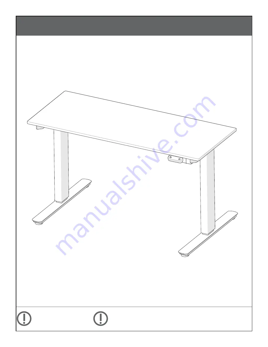
Up-Rite Electric Height Adjust Desk

UPDATED AS OF: 03/08/18

Part Number: 91153-A, 91153-B, 91153-C, 91153-D, 91153-E, 91153-F.

1 of 10

INSTRUCCIONES DE ENSEMBLAJE

NO LA TIRE

INSTRUCTIONS DE MONTAGE

NE PAS JETER

ASSEMBLY INSTRUCTIONS

DO NOT THROW AWAY!

Summary of Contents for 91153-A

Page 1: ...ght Adjust Desk UPDATED AS OF 03 08 18 Part Number 91153 A 91153 B 91153 C 91153 D 91153 E 91153 F 1 of 10 INSTRUCCIONES DE ENSEMBLAJE NO LA TIRE INSTRUCTIONS DE MONTAGE NE PAS JETER ASSEMBLY INSTRUCTIONS DO NOT THROW AWAY ...

Page 2: ... ASSEMBLY INSTRUCTIONS DO NOT THROW AWAY PARTS P2 L R P1 2x P3 L R HARDWARE B 8x M6 1 0 x12mm C 16x M6 1 0 x15mm D 2x M6 1 0 x75mm K 2x 3 16 Wood Screws L 4x 5 32 Wood Screws J 4 allen wrench H 2 5 allen wrench I 3 allen wrench P8 P9 P7 2x P6 P5 2x P4 P12 2x P10 4x P14 P13 A 8x M6 1 0 x10mm E 8x M6 1 0 x6mm ...

Page 3: ...partes y materiales necesarios Es posible que los muebles grandes o pesados requieran mas de una persona para ensamblarlos correctamente Por favor contacte al fabricante directamente si tiene alguna duda o pregunta antes de continuar con el proceso de armado del producto La garantía no cubrirá daños que ocurrieron por errores cometidos durante el proceso de ensamblaje Todos los tornillos deben est...

Page 4: ...STEP 1 Use 4 A screws to install foot to leg upright Repeat for both legs UPDATED AS OF 03 08 18 4 of 10 STEP 2 Screw glides into foot Repeat for both legs P2 P10 P1 A 4x J ...

Page 5: ... both legs Note Match L to L and R to R to ensure holes align UPDATED AS OF 03 08 18 5 of 10 STEP 4 Slide P5 square tube into leg crossbar assemblies Use black dots to center the square tubes P5 P3 B 4x J Use 4 more B screws on each side to further secure the leg to crossbar ...

Page 6: ... one end of the hexagonal rod through the motor P8 Push both ends of the rod assembly into the hole shown in each leg P8 P6 P7 P7 Loosen pre installed set screws on both hexagonal rods Slide the pointed end of the hexagonal rods into the round center rod ...

Page 7: ...AS OF 03 08 18 7 of 10 STEP 6 D 2x J J C 8x Align holes in the frame with inserts in the top Use 8 C screws to secure the frame to the table top NOTE Ensure the rods remains fully inserted to each leg If they do not that leg will not rise when adjusting desk height ...

Page 8: ...S OF 03 08 18 8 of 10 STEP 8 E 8x H H Center the round middle rod and slide the metal stops up against either end Tighten the two set screws to lock it in place Tighten 8 pre installed set screws to lock frame position ...

Page 9: ... 03 08 18 9 of 10 STEP 12 Use 2 K screws to mount the power brick bracket to the bottom of the table in desired location Use 4 L wood screws to install control panel in desired position on the bottom of the top P9 L 4x P14 ...

Page 10: ...cord into power brick Then into a nearby outlet being sure not to create a trip hazzard Use 2 K screw to install each plastic cord management clip in desired location Slide power brick into mount bracket Plug white plug from contol panel into motor through hole in leg bracket Plug remaining control panel wire into power brick wire P12 P13 P12 ...

Reviews: