Gemini 720is Imaging Sonar
Document: 0703-SOM-00002, Issue: 7
64
© Tritech International Ltd.
7. Seanet Pro Operation
Note
This section details the aspects of Seanet Pro that are specific to the Gemini
Sonar. For more general information (particularly if integrating with other
devices) please see the Seanet Pro Software Manual which is available online
at
www.tritech.co.uk
Before starting operations, run Seanet Setup to verify that the Gemini LAN is enabled and
any connected devices, including the Gemini sonar, are detected. In Seanet Pro, the Gemini
Sonar has been allocated the node range from 100 to 103.
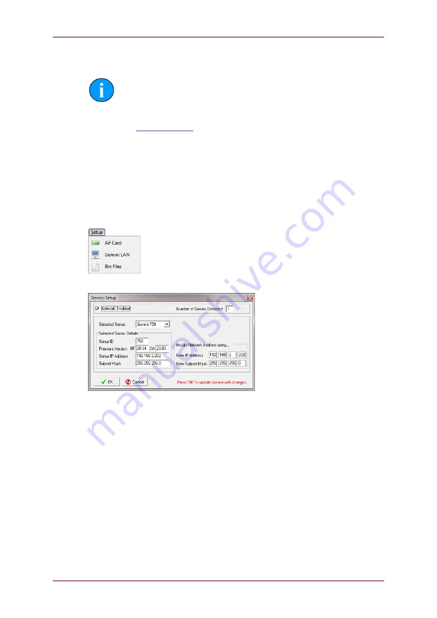
7.1. Seanet Setup for Gemini
Click on
Gemini LAN
from the
Setup
menu.
This will open the
Gemini Setup
page.
Gemini Setup
Network Enabled
Ensure this box is ticked to load the Gemini Connection
DLL and start the Gemini Network. The box can remain
permanently ticked thereafter.
Number of Sonars Detected
When the network is enabled, this will display the
number of Gemini Sonars that are currently detected and
broadcasting on the network.
Selected Sonar
The drop-down list will display the ID Numbers of all the
Gemini Sonars currently connected. Select the Gemini
Sonar that you wish to configure.
Selected Sonar Details
When the selected item in the ‘Selected Sonar’ drop-
down list is changed, the details of that particular Gemini
Sonar will be displayed here. These details include;
unique Sonar ID, Firmware Versions, broadcasting Sonar
IP Address and Subnet Mask.


