Connecting the System
Connecting the System
The following sections show system connections and cable diagrams for typical Class 6 M-
style EIP motors.
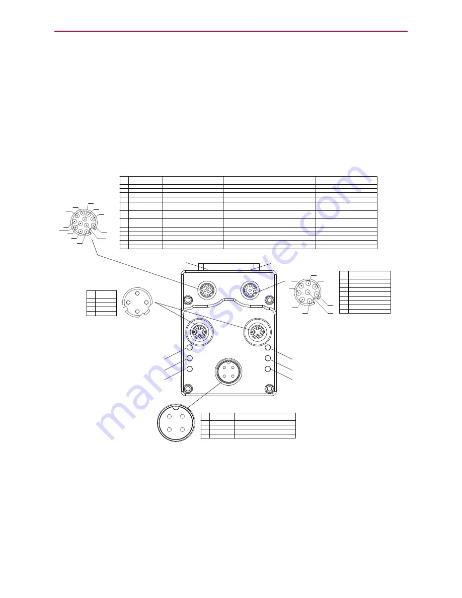
Class 6 M-Style EIP Motors: Connectors and Pinouts
The following figure provides a brief overview of the connectors and pinouts available on the
Class 6 M-style SmartMotors. Additional connector specifications are available in the
Class 6
SmartMotor™ Installation Guide
.
The EtherNet/IP (industrial Ethernet) ports are used to connect the motor to the Ethernet
network. See the figure below for the location of those ports.
1
2
3
4
POWER INPUT
PIN FUNCTION
DESCRIPTION
1
24 VDC
CONTROL I/O POWER
2
EARTH
CHASSIS GROUND
3
GND
MOTOR COMMON GROUND
4
48 VDC
MOTOR POWER
COMMUNICATION
PIN FUNCTION
1 GND-COMMON
2 RS-485B CH0
3 RS-485A CH0
4 ENC A+ (IN/OUT)
5 ENC B- (IN/OUT)
6 ENC A- (IN/OUT)
7 5 VDC OUT
8 ENC B+ (IN/OUT)
1
2
3
4
5
6
7
8
1
2
3
4
5
6
7
8
9
10
11
12
I/Os
PIN FUNCTION
DEFAULT
1 IN0
GENERAL PURPOSE
2 IN1
GENERAL PURPOSE
3 IN2/POSLIMIT
POSITIVE LIMIT
4 IN3/NEGLIMIT
NEGATIVE LIMIT
5 IN/OUT4
GENERAL PURPOSE
6 IN/OUT5
GENERAL PURPOSE
7 IN6
GENERAL PURPOSE
8 IN7-DRVEN
DRIVE ENABLE
9 OUT8/BRAKE
BRAKE OUTPUT
10 OUT9-NOFAULT
NOT FAULT
11 24 VDC OUT*
CONTROL I/O POWER
12
GND
MOTOR COMMON GROUND
INPUT OR OUTPUT
INPUT, DISCRETE OR ANALOG
POSSIBLE (SELECTABLE) FUNCTIONS
INPUT, DISCRETE OR ANALOG
INPUT
INPUT
INPUT/OUTPUT
INPUT/OUTPUT
INPUT
INPUT
OUTPUT
OUTPUT
POWER OUTPUT**
N/A
GENERAL PURPOSE
GENERAL PURPOSE
POSITIVE LIMIT OR GENERAL PURPOSE
NEGATIVE LIMIT OR GENERAL PURPOSE
GENERAL PURPOSE, OR EXTERNAL ENCODER
INDEX CAPTURE
GENERAL PURPOSE, OR INTERNAL ENCODER
INDEX CAPTURE
GENERAL PURPOSE, G COMMAND, OR
HOMING INPUT (ETHERCAT ONLY)
N/A
NOT FAULT
BRAKE OUTPUT OR GENERAL-PURPOSE OUTPUT
DRIVE ENABLE
*NOTE: 2 AMPS MAX **SUPPLIED FROM POWER INPUT PIN 1
CONTROL I/O POWER
RS-485 serial communication uses a
voltage differential signal. Appropriate
terminating resistors should be included
on the RS-485 network to ensure reliable
performance. For details, see the section
Power and RS-485 Com Multidrop.
1
2
3
4
Shield tied to motor
housing
LED 4: EtherNet/IP Link 1 Port LED
LED 2: EtherNet/IP Network Status LED
LED 0: Motor Drive LED
LED 5: Link EtherNet/IP Link 2 LED
LED 3: EtherNet/IP Module Status LED
LED 1: Motor Busy LED
USB Port LED
SD Card LED
EtherNet/IP
PIN FUNCTION
1
+TX
2 +RX
3 -TX
4 -RX
*Input
*Output
NOTE:
When daisy-chaining SmartMotors for an Ethernet Serial Encapsulation
network, there is no specific IN or OUT Ethernet port. In other words, either
Ethernet port can be used for the input or the output.
Moog Animatics Class 6 SmartMotor™ Ethernet Serial Encapsulation Guide, Rev. B
Page 12 of 32
Summary of Contents for Smart Motor SM23166MT
Page 31: ......
Page 32: ...PN SC80100017 001 Rev B Ethernet Serial Encapsulation ...


