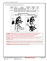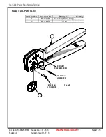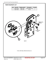
Tool Kit for P-Lock Flag Female Terminal
Doc No: ATS-6382566HM Release Date: 01-27-13
UNCONTROLLED COPY
Page 3 of 8
Revision: A
Revision Date: 01-27-13
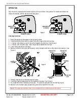
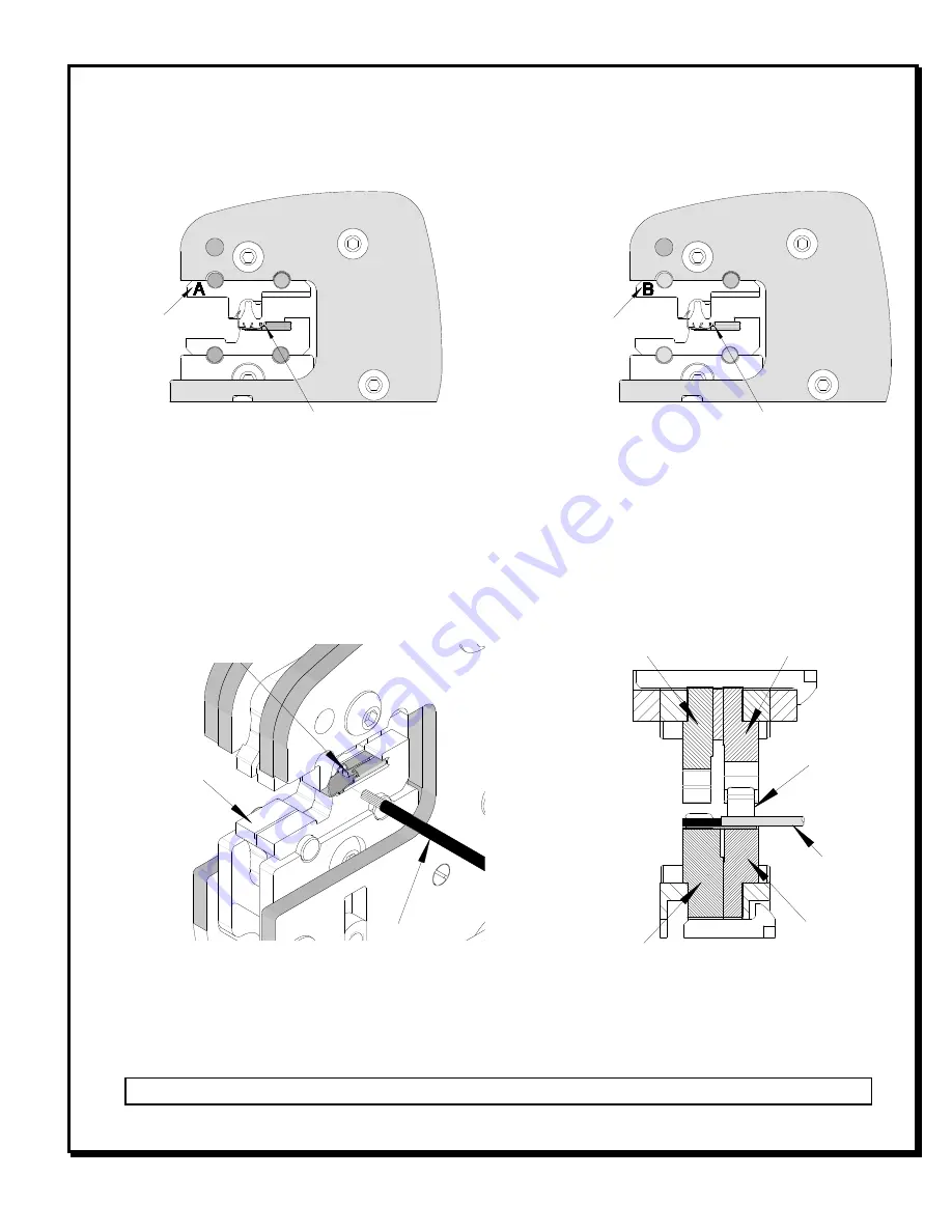
MARKING FOR
AWG24
Figure 3
TERMINAL IN NEST
MARKING FOR
2x AWG24
TERMINAL IN NEST
Figure 4
PARTIALLY
CLOSED
WIRE
TERMINAL
WIRE
INSULATION
PUNCH
CONDUCTOR
ANVIL
INSULATION
ANVIL
CONDUCTOR
PUNCH
TERMINAL
OPERATION
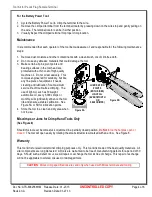
Open the tool by squeezing the handles together, at the end of the closing stroke, the ratchet mechanism will
release the handles, and the hand tool will spring open.
Crimping Terminals
1.
Select the desired terminal listed in the preceding charts.
2.
Insert the terminal centered in the proper nest and up against the terminal stop.
3.
●
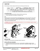
If using a 24 AWG wire, load in the profile marked A from the front. See Figure 2.
4.
●
If using a 24 + 24 AWG wires, load in the profile marked B from the front.
5.
Lower tooling nest does not change.
6.
Make sure when choosing the nest opening, it will correspond with the A or B profile on the hand tool. See
Figure 3.
7.
Partially close the tool to hold the terminal in place.
8.
Insert the properly stripped wire into the insulation crimp nest. See Figure 4.
9.
Now close the handle completely and release. The jaws will open when the tool has fully closed.
10.
Make sure the insulation grips wrapped snug around the insulation of the wire.
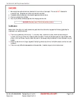
Note
: The tamper proof ratchet action will not release the tool until it has been fully closed.


