C-Grid® SL™ FFC Termination Kit
Doc. No: TM-638018550
Release Date: 03-11-13
UNCONTROLLED COPY
Page 1 of 23
Revision: B
Revision Date: 11-23-15
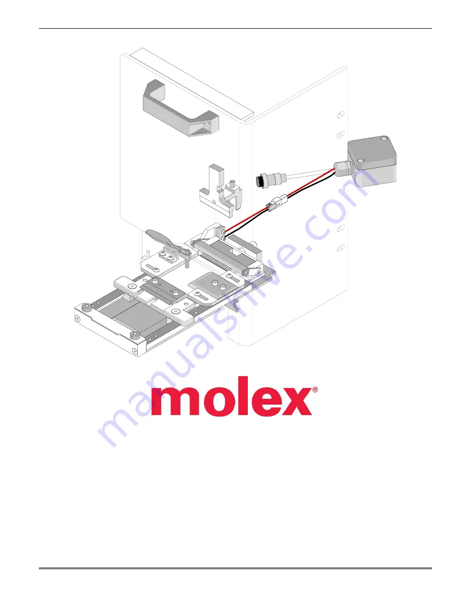
C-Grid® SL™ FFC Termination Kit
(For T2 and Terminator Crimp Module)
Order No. 63801-8550
Instruction Manual
Description
Operation
Maintenance


