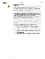
3.6 Electrical Lockout
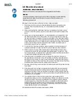
WARNING - READ MANUAL
Refer to all machine manuals and local regulations and codes.
NOTE
In some instances, there may be more than one power source feeding
equipment and steps must be taken to ensure that all sources are
effectively locked out.
Employers must provide an effective lockout / tagout program.
1. Shut down machine using normal operational shutdown procedure and
controls. This should be done by, or in consultation with the machine
operator.
2. After ensuring that the machinery has been completely shut down, and all
controls in the “off” position, open the main disconnect switch located in the
field.
3. Using your own personal padlock, or one assigned by your supervisor, lock
the disconnect switch in the off position. Do not lock only the box. Remove
the key and retain. Complete a lockout tag and affix to the disconnect switch.
Each person working on the equipment must follow this step. The lock of the
person doing the work or in charge must be installed first, remain throughout
and be removed last. Test the main disconnect switch and make sure it
cannot be moved to the “on” position.
4. Try to start the machine using the normal operation controls and point of
operation switches to make sure that the power has been disconnected.
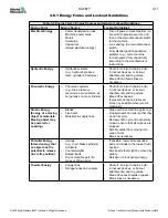
5. Other sources of energy that could create a hazard while working on the
equipment must also be de-energized and appropriately “locked-out”. This
can include gravity, compressed air, hydraulics, steam and other pressurized
or hazardous liquids and gases. See Table 3-3.
6. When the work is completed, prior to removing the last lock, make sure
the operational controls are in the “off” position so that the main disconnect
switching is done under “no load”. Ensure all blocks, tools and other foreign
materials are removed from machine. Also ensure that all personnel that may
be affected are informed that the lock(s) will be removed.
7. Remove lock and tag, and close the main disconnect switch if permission has
been given.
8.
When the work has not been completed on the first shift, the next operator
should install a personal lock and tag before the first operator removes the
original lock and tag. If the next operator is delayed, a lock and tag could be
installed by the next supervisor. Lockout procedures should indicate how the
transfer is to be conducted.
9. It is important that, for their personal protection, each worker and/or
foreperson working in or on a machine places his/her own safety lock on the
disconnect switch. Use tags to spotlight work in progress and give details
of work being done. Only when the work is completed and the work
permit
signed off, may each worker remove his/her lock. The last lock to be
removed should be that of the person supervising the lockout and this
responsibility should not be delegated.
© Industrial Accident Prevention Association, 2008.
3-10
E-Drive Controller User Manual (with Pendant HMI)
SAFETY
© 2020 Mold-Masters (2007) Limited. All Rights Reserved.
Summary of Contents for E-Drive Series
Page 1: ...version 3 User Manual with Pendant HMI Original Instructions ...
Page 2: ......
Page 26: ......
Page 36: ......


