background image

V092420

SET-UP • OPERATION • MAINTENANCE • SERVICE • TROUBLESHOOTING • WARRANTY

READ AND FOLLOW ALL SAFETY RULES AND INSTRUCTIONS IN THIS MANUAL

BEFORE ATTEMPTING TO OPERATE THIS MACHINE. FAILURE TO COMPLY WITH THESE  

INSTRUCTIONS MAY RESULT IN PERSONAL INJURY.

WARNING

Summary of Contents for ZR 350

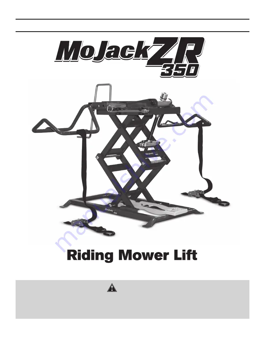
Page 1: ...INTENANCE SERVICE TROUBLESHOOTING WARRANTY READ AND FOLLOW ALL SAFETY RULES AND INSTRUCTIONS IN THIS MANUAL BEFORE ATTEMPTING TO OPERATE THIS MACHINE FAILURE TO COMPLY WITH THESE INSTRUCTIONS MAY RESULT IN PERSONAL INJURY WARNING ...

Page 2: ...r Customer Service Department is ready to help 1 877 575 3173 U S Patent 8 448 920 Distributed By MoJack Distributors 3535 N Rock Road Wichita KS 67226 For Customer Support call 1 877 575 3173 themojack com ...

Page 3: ...g these operating maintenance and safety instructions you will prolong the life of your MoJack lift and promote safe operation If additional information is needed contact MoJack Distributors customer service at 1 877 575 3173 Parts are thoroughly tested and inspected before leaving the factory to ensure they comply with all relevant safety standards NOTE Please save this manual for future referenc...

Page 4: ...19 to 43 5 Always stop engine and remove key before beginning any work on the mower Always place mower in neutral or disengage the hydraulic drive by following the mower owner s manual Never operate the engine while using the mower lift Do not exceed the lifting capacity of 350 lbs front end weight If the mower steel pin breaks allowing the crank handle to spin freely while lifting the mower this ...

Page 5: ...Y FROM STATE TO STATE OR PROVINCE TO PROVINCE What does this warranty cover This warranty covers against a failure due to a defect in material or workmanship within two years of purchase for residential use and within one year of purchase for commercial use What does this warranty NOT cover This warranty does not cover any jack which has been altered or adjusted in any way from its original model ...

Page 6: ...el Pad Crank Handle Safety Strap Push Pin Steel Pin 508 0000 508 0044 508 0035 009 0007 001 0013 001 0015 6 1 2 1 2 2 2 Spares Item No 1 2 3 4 1 4 NOTE No tools or fasteners are required for assembly NOTE Steel Pin is attached to the user manual see page 10 for location 4 3 2 2 5 5 6 ...

Page 7: ... into the square tube on the top of the Scissor Frame and install Push Pins Repeat with second Wheel Pad ASSEMBLY INSTRUCTIONS STEP 1 Remove mower lift from package Inventory items to be certain all parts and hardware are present If any parts or hardware are missing please contact customer service at 1 877 575 3173 Scissor Frame 1 2 1 Wheel Pad 2 STEP 2 5 Push Pin 5 STEP 3 3 3 Crank Handle 3 THIS ...

Page 8: ...ntirety STEP 1 Familiarize Yourself with the Mower Lift Practice raising and lowering the mower lift before attempting to lift a mower see Steps 5 8 on how to raise and lower a mower Locking bar must be raised before lowering Practice Step 10 if you intend to raise or lower the mower with a drill attachment ...

Page 9: ...r tires to the Wheel Pads using the Safety Straps Wrap the Safety Strap over the mower tire and secure the hook into the loop on the Wheel Pad Tighten the Safety Straps by pressing down on the metal clip 4 Safety Strap 4 Wheel Pad 2 STEP 2 Aligning Wheel Pads to Fit Mower Place the mower lift wheel pads 6 in front of the mower s front tires Remove Push Pins and align the Wheel Pads so that the fro...

Page 10: ...s to wheel pads NOTE The mower lift is equipped with a Steel Pin to protect against overload If the mower lift is overloaded with too much weight the Steel Pin will break and release the Crank Handle from the screw and allow the Crank handle to rotate freely If this happens a new Steel Pin will need to be installed Replacement of Steel Pin Remove the rubber O Ring retainer Slide out the broken Ste...

Page 11: ...ck tires of the mower Apply the parking brake on the mower The lower axle must be engaged in one of the notches of the Locking Bar Wheel Chock STEP 8 Lowering the Mower Remove Wheel Chocks Release the parking brake Mower must be in neutral or hydraulic drive disengaged Lift up and hold the Locking Bar with your foot and turn the Crank Handle clockwise until the wheel pads are firmly on the ground ...

Page 12: ...um The drill will require a 3 8 square driver not included Remove Crank Handle Firmly insert the 3 8 square driver in the Square Receiver Rotate the drill reverse counterclockwise to raise the Lift Arm and rotate the drill in forward clockwise to lower the Lift Arm Locking Bar must be lifted and held up until it clears the last notch during lowering Operator must have a firm grip on the drill befo...

Page 13: ...st once a year using light machine oil Place lithium grease between all the pivot points after every 50 uses or once a year Add a few drops of light machine oil to the Thrust Bearing after every 50 uses or once a year Clean and oil Screw Thread Wheel Pad 2 Push Pin 5 Preparing the Mower Lift for Storage Remove the Push Pins slide the Wheel Pads to the narrowest position and reinsert the Push Pins ...

Page 14: ...14 ...

Page 15: ...15 ...

Page 16: ...Distributed By MoJack Distributors 3535 N Rock Road Wichita KS 67226 For Customer Support call 1 877 575 3173 themojack com ...

Reviews: