


Hardware
Device Description Embedded HMI-PLC XV-23x-57
Mounting instructions
9 M
OUNTING INSTRUCTIONS
9.1 G
ENERAL MOUNTING INSTRUCTIONS
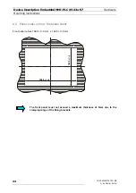
All devices are installed from the front, for example, into a control panel.
Standard front
The device is fixed from the rear with at least 4 fixing brackets (M4 threaded pin with type 2 hexagon).
Four additional fixing brackets are required for mounting to IP 65.
The devices can be run at a maximum ambient temperature of 50°C. This refers to the area directly
next to the lower cooling slots when the device is mounted vertically. A clearance of 3 cm must be
maintained at the cooling slots on all sides to ensure unobstructed air convection.
Hot components such as a heavily loaded transformer must have a clearance of at least 15 cm.
Avoid the exposure of the flat screen to direct sunlight. The sunlight (UV component) reduces the
lifespan of the LCD crystals.
The cooling slots must always be free in order to ensure the proper cooling of the
system.
Avoid the exposure of the flat screen to direct sunlight.
Ensure that operating elements (Control button, CF card) and terminals are still
accessible when the device is mounted.
The front panel must not exceed a maximum thickness of 5mm due to the clamping
range of the fixing brackets.
Mounting techniques not listed in this description should only be carried out with
the permission of the supplier.
The maximum torque for tightening the fixing brackets is 0.15 Nm.
12/05 AWB2776-1581GB
© by Moeller GmbH
21