


01/08 AWB2190-1430GB
Installation
41
Wiring and connections
AS-Interface
®
connection
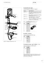
Connection through plug M12
Before establishing the connection to AS-Interface®, you can
assign the AS-Interface® address through plug M12 with an
addressing device,
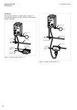
Mounting
X
Unscrew the cover of the disconnect control unit RA-DI and
disconnect the AS-Interface
®
plug from the circuit-board.
X
Open the required knockout and insert and tighten cable gland
V-M20 or V-M25.
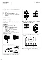
X
Secure the bottom section with two M5 screws (see fig. 39).
X
Remove the cover plate.
X
Feed a 7
x
2.5 or 7
x
4 mm
2
round cable (T1, T2, T3, N, PE,
24 V, 0 V) in to the busbar, fit the connectors and connect it as
shown in figure 38.
X
Fed the round cable(s) 5
x
2.5/4/6 mm
2
(L1, L2, L3, N, PE) and
2
x
2.5/4/6 mm
2
(24 V, 0 V) or alternatively 7
x
2.5/4 mm
2
(L1, L2, L3, N, PE, 24 V, 0 V) in to the busbar, fit the connectors
and connect them as shown in figure 38.
X
For additional protection of AS-Interface
®
from loosened
cables, fit the cover plate. The procedure is described in fig. 41.
X
Fit the plug in the AS-Interface
®
circuit-board.
X
Close the cover and secure it with the screws.
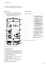
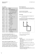
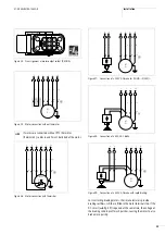
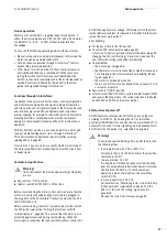
Figure 38: Wiring of disconnect control unit
(for legend, see figure 37)
PIN
Function
1
ASi+
2
–
3
ASi–
4
–
L1
POWER
1
2
3
4
5
6
L2
L3
N
N
0 V
L1
L2
L3
T1
T2
T3
1.13 1.21
1.14 1.22
+24 V
I+24 V
I1
I2
I3
I4
PE
PE
I
>
I
>
I
>
+24 V
0 V
h
e
f
a
g
b
i
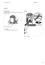
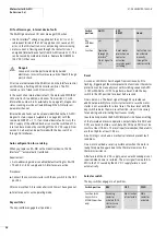
Figure 39: Mounting
o
[mm]
Thread
Torque [Nm]
5,5
M5
3
o
5
Summary of Contents for Rapid Link
Page 10: ...01 08 AWB2190 1430GB 6 ...
Page 40: ...01 08 AWB2190 1430GB 36 ...
Page 48: ...01 08 AWB2190 1430GB 44 ...
Page 70: ...01 08 AWB2190 1430GB 66 ...
Page 146: ...01 08 AWB2190 1430GB 142 ...
Page 162: ...01 08 AWB2190 1430GB 158 ...