


Incoming circuit-breaker RA-DI
01/08 AWB2190-1430GB
40
Installation
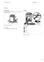
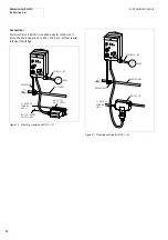
Mounting position
The device is preferably installed vertically but can also be fitted in
the positions shown in the illustration.
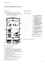
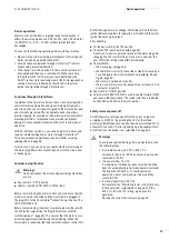
Design
Figure 36: Mounting position
F
90
F
90
F
90
F
90
Figure 37: Design (internal view)
a
N, tightening torque 2 Nm
b
L1, L2, L3, tightening torque 1.8 Nm, to 6 mm
2
c
overload release
I
r
d
short-circuit release
I
rm
e
T1, T2, T3, tightening torque 1.8 Nm, to 6 mm
2
f
PE, tightening torque 2 Nm
g
24 V DC standard auxiliary contact NHI11, contact 1.14, tightening
torque 1 Nm, for conductor cross-sections > 2.5 mm
2
use with
supplied pin-end connector
h
0 V terminal (K10/1) for 1.5 to 6 mm
2
, tightening torque 0.8 Nm
i
24 V DC standard auxiliary contact NHI11, contact 1.13, tightening
torque 1 Nm (for conductor cross-sections > 2.5 mm
2
use with
supplied pin-end connector)
b
a
c
d
e
f
i
g
h
Summary of Contents for Rapid Link
Page 10: ...01 08 AWB2190 1430GB 6 ...
Page 40: ...01 08 AWB2190 1430GB 36 ...
Page 48: ...01 08 AWB2190 1430GB 44 ...
Page 70: ...01 08 AWB2190 1430GB 66 ...
Page 146: ...01 08 AWB2190 1430GB 142 ...
Page 162: ...01 08 AWB2190 1430GB 158 ...