


01/08 AWB2190-1430GB
Engineering
39
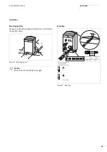
Settings on the device
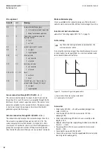
Response value of non-delayed short-circuit release
•
I
rm
= 130 A
(minimum mark, factory default)
•
I
rm
= 210 A
(maximum mark)
Setting of overload release
•
I
r
= 20 A for 1 cable cross-section 2.5 mm
2
•
I
r
= 20 to 25 A for 1 cable cross-section 4 mm
2
With these settings the requirements of the following standards
are fulfilled:
• IEC/EN 60947-4-1, type “1” coordination with motor control
unit RA-MO
• DIN VDE 0100 Part 430.
Core insulation
The core insulation of all used conductors must be laid out for the
highest operational voltage occurring in the unit.
Safe isolation
To ensure safe PELV isolation between voltages 24 V
H
and
400 V
h
of the control and main circuits and the AS-Interface
®
voltage, use only the correct provided connections.
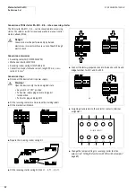
For additional protection against loosening of cables, fit the cover
plate (
a
figure 41 on Page 42).
Accessories
Metric cable glands M20 (V-M20) and M25 (V-M25).
Information to EMC
For information about EMC, see the following sections of this
manual.
Figure 35: Settings on the device
PKZ2/ZM-25-8
Z 2
2
x
I
rm
I
r
Summary of Contents for Rapid Link
Page 10: ...01 08 AWB2190 1430GB 6 ...
Page 40: ...01 08 AWB2190 1430GB 36 ...
Page 48: ...01 08 AWB2190 1430GB 44 ...
Page 70: ...01 08 AWB2190 1430GB 66 ...
Page 146: ...01 08 AWB2190 1430GB 142 ...
Page 162: ...01 08 AWB2190 1430GB 158 ...