


01/08 AWB2190-1430GB
Device operation
29
as-interface
®
X
Connect the RA-IN unit to the AS-Interface
®
through the M12
plug.
Connecting the power supply
Dimensioning the 30 V supply line
Choose a 30 V DC power supply cable that keeps the voltage drop
between PSU and RA-IN as low as possible: a reduced supply
voltage at the RA-IN unit can limit the possible cable length of the
AS-Interface
®
run. For information about calculating the voltage
drop, see page 12.
Device operation
Device startup
When you fist switch on the device, all segments of the digital
display and all LEDs light up for about one second (self-test). After
that, the LEDs indicated the state of the respective flags. The
digital display indicates the interface control unit’s status.
They have the following meaning:
h
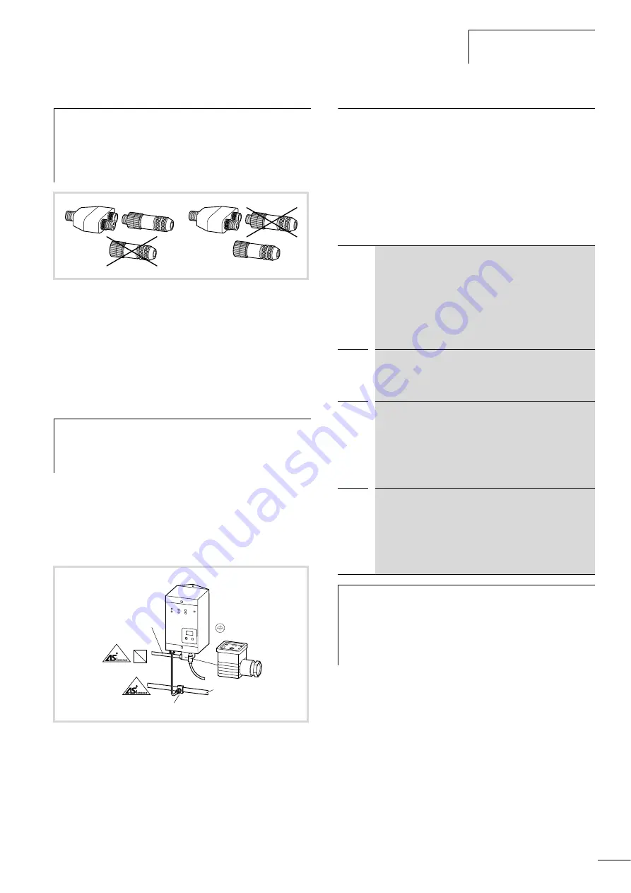
Note the combinations:
For space reasons, you can only connect the RA-IN-XY-DP
Y connector to one RA-IN-XM-DP user-assembled plug or
RA-IN-XF-DP coupling in combination with a RA-IN-XTR-
DP terminating resistor or a prefabricated M12 cable.
Figure 30: Combination options on RA-IN-XY-DP
h
The interface control unit is connected to an external
30 V DC PSU through the supplied power socket. Degree
of protection IP65 is achieved only when the unit is fully
assembled.
Figure 31: Connection to AS-Interface
®
and
30 V
H
ZB2-155-KB1
SELV
ZB2-100-AZ1
3
x
1.5 mm
2
(3
x
2.5 mm
2
)
o
6 – 9 mm
30 V
H
=
h
1 = 30 V
H
2 = 0 V
OFP
offline-phase
RA-IN is being initialized; no data exchange through
AS-Interface
®
(see warning note under table).
In Engineering mode or automatic start of the AS-Interface
®
,
the unit can leave the offline phase. Accordingly, if PROFIBUS
communication is interrupted in protected operation mode,
RA-IN changes to offline phase when the watchdog time set
on the PROFIBUS master has expired.
SEA
Detection phase
Start of startup operation, in which the unit searches for
existing slaves. RA-IN remains in detection phase until it
detects at least one slave.
42
Activation phase
State at the end of detection phase, in which the parameters
for all connected and detected AS-Interface
®
slaves are
transmitted. This enables access to the data connections in
the AS-Interface
®
slaves. The activation phase and the start
of normal operation can be so short that they are not
displayed.
43
Start of normal operation
In normal operation RA-IN exchanges data with all active
slaves, transmits management messages from and to the
host) and searches for or activates newly connected slaves.
During normal operation the maximum cycle time of 10 ms
for 62 slaves is maintained for reading and writing the AS-
Interface
®
data.
h
Caution!
RA-IN remains in offline phase if the
AS-Interface
®
circuit is not supplied with sufficient
voltage (“UAS-i” not lit) or there is no PROFIBUS
communication between the PROFIBUS master and the
RA-IN.
Summary of Contents for Rapid Link
Page 10: ...01 08 AWB2190 1430GB 6 ...
Page 40: ...01 08 AWB2190 1430GB 36 ...
Page 48: ...01 08 AWB2190 1430GB 44 ...
Page 70: ...01 08 AWB2190 1430GB 66 ...
Page 146: ...01 08 AWB2190 1430GB 142 ...
Page 162: ...01 08 AWB2190 1430GB 158 ...