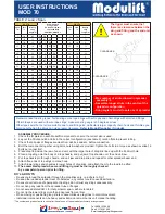
USER INSTRUCTIONS
MOD 70
WARNING!
Personnel using this system should be suitably trained, competent and have a clear
understanding of Safe Slinging procedures.
The use of Modulift equipment must be in accordance with the procedures laid down in ‘Lifting
Operations and Lifting Equipment Regulations 1998’ (LOLER).
NEVER EXCEED STATED SWL - ADHERE TO SWL IN TABLE 2, FOR PARTICULAR SLING
ANGLE USED
THE TOP SLING LENGTH IS CRITICAL TO THE SAFE USE OF THE SPREADER - ADHERE
TO TABLE 2.
Ensure Drop Links hang down, and smaller shackles are connected to bottom hole of Drop Link.
Do not under any circumstances hang load(s) from the tube or flanges - the spreader is designed
for axial compression - not bending.
MOD 70 - Beam Specification.
Rated at 70 tonnes SWL at 9 metres span (
30° STV)
. See Load Table for SWL at longer spans.
‘Sling to Vertical’ angle,
β
,
45 degrees or less.
End Units & Drop Links are rated at 35 tonnes WLL each (70 tonnes combined capacity).
Bolt tightening torque: 150Nm.
Spanner size required: 30mm.
Recommended additional equipment: Torque Wrench, Podger Spanner and Ring Spanner.
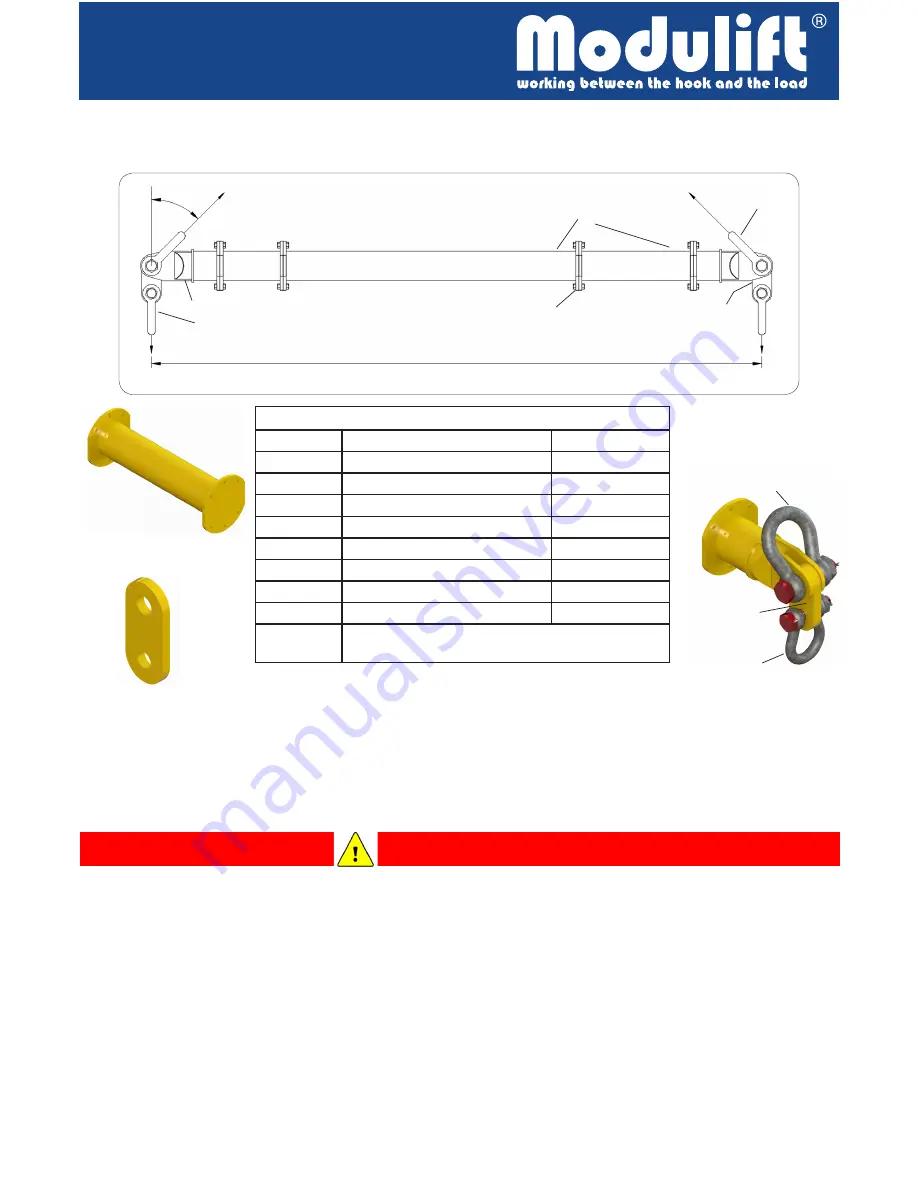
The Modulift Spreader is modular in length. Every spreader consists of 1 pair of End Units & Drop
Links, with intermediate struts that can be bolted into the assembly to achieve different spans. The
MOD 70 has an assembled span ranging from 1 metre to 12 metres in 0.5 metre increments.
TABLE 1: COMPONENT LIST
PART REF: DESCRIPTION
WEIGHT / ITEM
P1
END UNIT
56kg
P2
DROP LINK
17kg
P3
4.0m STRUT
240kg
P4
2.0m STRUT
136kg
P5
1.0m STRUT
85kg
P6
0.5m STRUT
61kg
P7
55t SHACKLE
40kg
P8
35t SHACKLE
20kg
P9
M20x65, GRADE 8.8 HT BOLTS, NUTS &
WASHERS
DROP
LINK
STRUT
END UNIT
SUB-ASSY
Smaller
shackle
Larger
shackle
Drop
Link
Fig.1: Typical Spreader Assembly.
P7
P9
P2
P1
P3 - P6
P8
b
Fig. 1: Typical Spreader Assembly.
β
=’Sling to Vertical’ angle
Span


