

pGD1
Remote
Display
Function
Description
ALARM
When one or more alarms are active the ALARM button will blink/flash red.
Pressing the ALARM button once will indicate information regarding any active alarms.
Pressing the ALARM button twice will reset any active manual-reset alarms.
PRG
Pressing the PRG button will select the main navigation menu.
ESC
Pressing the ESC button will return the user to the main display screen showing unit status.
UP
Pressing the UP button can either:
Scroll through the various display screens, provided the cursor is in the top left position.
Increase the value of a setpoint adjustment.
ENTER
Pressing the ENTER button will confirm any setpoint adjustments and move the cursor to the next available setpoint.
DOWN
Pressing the DOWN button can either:
Scroll through the various display screens, provided the cursor is in the top left position.
Decrease the value of a setpoint adjustment.
Modine Controls System Quickstart Guide
Airedale ClassMate
®
(CMD/CMP/CMS) and SchoolMate
®
(SMG/SMW)
This guide is designed to walk through the basics of establishing unit setpoints and
scheduling for a ClassMate or SchoolMate unit using the pGD1 display module. Every unit
with Modine Controls System is designed for either standalone or networked operation. For
units communicating on a BMS, the guide will also explain how to adjust your unit’s device
instance to allow proper communication.
The pGD1 display module can be unit mounted, or handheld depending on the customized
order. The pGD1 allows for complete visibility over the unit’s controls parameters. It is
recommended that at least one handheld device be available at the install site if the need
arises to change these settings.
Please reference AIR74-525 Modine Controls System Manual for more in-depth information.
a. Install unit in desired location in accordance with appropriate Modine Installation and Maintenance Manual.
Note: Controller will not be powered until unit
has appropriate electrical connections and disconnect switch in “ON” position.
b. If display module is not unit mounted, connect pGD1 handheld module using RJ-12 communication cable provided in port J15 as shown on unit mounted
wiring diagram.
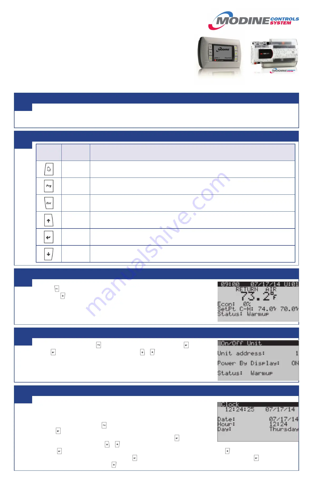
a. The main
screen (shown at right) is the default navigation page, and can always be recalled by
pressing
. This may need to be pressed more than once depending on which menu is active.
b. By pressing you are able to scroll through the display screens which provide information about the
current system operation (examples include temperatures, output status, and space demand).
i.
OVERRIDE MODE:
Unit can be placed in override mode on the ‘Scheduler’ screen (unit will run in
occupied mode, regardless of clock schedule) by moving the cursor to the “Clock Override” field
and changing the value to ‘ON’. The override mode duration can be set on this same screen, and is
defaulted to 1 hour.
a. Enter the main menu by pressing and scroll down to line ‘A. On/Off Unit’ and press .
b. Press to move cursor, to ‘Power By Display’ line and the or arrow to change the value
between ‘ON’ and ‘OFF’. This parameter must be ‘ON’ for unit to have any functionality (shown at right).
a. Customizing the 7-Day Schedule
i. For units running without BMS communication, the controller has a preset 7-day schedule defined by
the internal timeclock. The unit will run in occupied mode from 6:00am to 4:00pm, Monday through
Friday, with no holidays.
ii. Enter the main menu by pressing and scroll down to line ‘C. Clock/Scheduler’ (shown at right)and
press .
iii. The first screen displays the current date and time. If this is not correct press to highlight the field
that needs to be changed. Use the or arrows to adjust the number as needed.
iv. Press to move through adjustable setpoints until cursor is at the upper left corner of the screen. Use the arrow to scroll to the next page.
v. Select the amount of schedules desires by pressing to highlight ‘Number of Schedules’ field and adjust the number. Press until cursor is at the
upper left corner of the screen. Use the arrow to scroll to the next page.
Begin
Navigating the Display Module Screen
Main Screen and System Status
Turning Unit On / Off
Schedule
1
2
3
4
5
(CONTINUED ON OTHER SIDE)
5H104617
pGD1 Display Module
Controller