background image

© MOBATIME 

9 / 16 

800945.06 


Connect the conductors to the terminal block on the clock body, in accordance with 
the descriptive nameplate (chapter 2.5). Give an appropriate shape to the 
conductors or cut them off at a length which does not obstruct the mounting of the 
clock into the clock body.  


Carefully shape all incoming cables into the clocks and secure them by screwing 
the cable clamp. 


Mount the connectors to the cable of the temperature sensor, to the keyboard 
cable, Ethernet cable or the RS 232 and RS 485 interface connectors, if these are 
used.  


Push the temperature sensor connector, the keyboard connector, Ethernet 
connector or the RS 232 and RS 485 jacks into the corresponding terminals on the 
control PCB (DC user manual chapters 2.8, 2.9). Check the marking of the jack-
plugs, in order to prevent their mix-up. 


Connect the interconnecting cables into the corresponding terminals on the clock 
control PCB. Reconnect the earth wire to connect the clock body to the front panel.  


Put the front panel into the clock body. Care should be taken when placing the 
cables between the clock body edge and the back side of the display front panel, 
so as not to nip them. 


SLH-DC..N.S   


cut


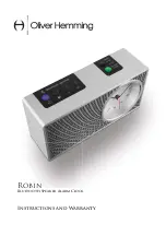
2.4  Flush mounting single-sided stainless-steel clock 


The clock consists of two parts. Visible front stainless-steel panel with display and 
back stainless-steel body with connecting terminal block. Both parts of the clock 
are held together by neodymium magnets.  


Remove the front panel from the clock body. 

The panel is held by magnets, you 

need to use a relatively high force to remove it. 


Summary of Contents for SLH-DC series

Page 1: ...MOBATIME BE 800945 06 INSTRUCTION MANUAL State of the art technology digital clock SLH DC series addition to the standard DC series instruction manual for SLH DC only...

Page 2: ...order to explain all details in respect of the operation of the product Should you nevertheless have questions or discover errors on this manual please contact us 3 We do not answer for direct or ind...

Page 3: ...single sided stainless steel clock 8 2 4 Flush mounting single sided stainless steel clock 9 2 5 Connecting terminal block 11 16 Engineering data 12 16 1 Standard design of the clock 12 16 2 Voltage...

Page 4: ...ion thanks to magnetic system easily washable with water high resistance to washing disinfectants anti glare polycarbonate front glass prevents glare and improves readability dust proof housing splash...

Page 5: ...cified value with stop at zero with automatic restart or counting into negative values display of intermediate time values freezing of display cumulated intermediate time counting in steps of 1 minute...

Page 6: ...e clock body to the wall On mains powered clock loosen the screw on the underside of the 230 VAC terminal cover and remove the cover Unscrew the cable clamp Connect the incoming conductors in accordan...

Page 7: ...front panel from the clock body The panel is held by magnets you need to use a relatively high force to remove it Disconnect the interconnecting cables by decoupling the terminals on the control PCB D...

Page 8: ...terminal block The front panel is held together by neodymium magnets The clock suspension part is delivered separately Pull the incoming conductors through the pipe which serves as the clock suspensio...

Page 9: ...ng terminals on the control PCB DC user manual chapters 2 8 2 9 Check the marking of the jack plugs in order to prevent their mix up Connect the interconnecting cables into the corresponding terminals...

Page 10: ...appropriate shape or cut them off to a length that will not obstruct the placement of the front part of the clock into the clock body On mains powered clock mount the 230 VAC terminal cover back and s...

Page 11: ...MOBATIME 11 16 800945 06 SLH DC N F wall niche mounting cut 2 5 Connecting terminal block terminal block for NTP and WiFI version terminal block for remaining version except PoE...

Page 12: ...ut synchronization after 24 hours of synchronization at constant temperature Accuracy of temperature meassurement range 10 85 C 0 5 C range 50 125 C 2 0 C Operating environment temperature 5 50 C humi...

Page 13: ...yboard SKH SKW SKF SKF back cover dimension W1 x H1 Dimensions mm W x H x D 80 x 180 x 42 4 120 x 120 x 47 82 x 152 x 50 67 x 139 Type of slave line Voltage range Electric current consumption MOBALine...

Page 14: ...on t use synthetics 19 DISPOSAL OF USED BATTERIES The user is lawfully obligated to return unusable batteries Disposal of used batteries through household waste is prohibited Batteries which contain d...

Page 15: ...ent according to the corresponding norm The following circumstances are excluded from the guarantee inappropriate handling or interventions chemical influences mechanical defects external environmenta...

Page 16: ...ch www mobatime ch MOSER BAER SA EXPORT DIVISION 19 ch du Champ des Filles CH 1228 Plan les Ouates Tel 41 22 884 96 11 Fax 41 22 884 96 90 export mobatime com www mobatime com MOSER BAER AG Spitalstra...

Reviews: