ML System Two D Series Installation And Service Manual Download Page 21

System Two LED Installation and Service Manual (1003385 Rev. C)


Page 21


Section 3 

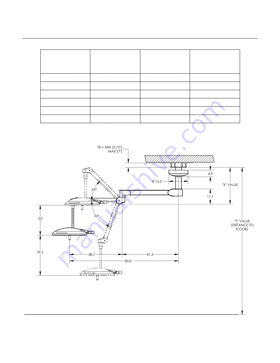
Ceiling Rod Calculation, Single Mount 

Use the following table to select the correct length ceiling rod for your application 

Ceiling Mounting 

Height 

“Y”-Value 

Ceiling Rod 

Length 

“X"-Value 

Head Room to 

Bottom of Extension 

Arm 

“Y”-Value – X-Value 

9'0”/108” 

8” 

19” 

89” 

9'6"

/114” 

16" 

27

” 

87

” 

10'0”/120” 

24" 

35

” 

85” 

10'6"

/126” 

32" 

43

” 

83” 

11'0”/132” 

39" 

50

” 

82

” 

12'0”/144” 

47" 

58” 

86

” 


Summary of Contents for System Two D Series

Page 1: ...INSTALLATION AND SERVICE MANUAL...

Page 2: ...rticular requirements for the safety of surgical luminaries and luminaries for diagnosis In accordance with IEC 60601 2 41 Intended use Professional Medical Lighting for Hospital Clinic Minor Surgery...

Page 3: ...System Two LED Installation and Service Manual 1003385 Rev C Page 3 Versions Height adjustment Brakes...

Page 4: ...cal 1 Ceiling Cover There are two Covers available The Standard Ceiling Cover is sufficient in most basic installations The large Ceiling Cover should be used when needed to cover a larger area 2 Ceil...

Page 5: ...uctions apply to System Two LED Surgical Light and Central Axis S1 System Two LED Surgical Light and Central Axis S2 System Two LED Surgical Light and Central Axis S3 Please do not hesitate to contact...

Page 6: ...t take any liability for or in relation to the misuse of this information in the prohibited manner by any person or company Modifications and translations MI products are subject to continuous further...

Page 7: ...Spring Arm 33 Preparing the L17 Spring Arm 35 Mounting the Light Head to L17 Spring Arm 36 Preparing the LCH Spring Arm 37 Mounting the Light Head to LCH Spring Arm 38 Positioning the Light 39 Section...

Page 8: ...Extension Arm 42 Figure 21 Dismantling the decorative caps and socket covers 43 Figure 22 Adjusting the brakes 43 Figure 23 Mounting the socket covers and decorative caps to the Extension Arms 44 Fig...

Page 9: ...hysical authority over the appliance during operation The operator shall be liable for handing over a safe appliance and for instructing the user in the proper operation and normal use of the applianc...

Page 10: ...a person designated by the operator On completion of the instruction a certificate must be created and signed in order to document that the user has understood the special operator control actions re...

Page 11: ...medical personnel The system may only be cleaned and disinfected by instructed hygiene specialists Maintenance work on the system must be carried out by the operator s technical specialist personnel i...

Page 12: ...ical personnel The color temperature of the light fixture when compared to a blackbody radiator expressed in degrees Kelvin The total amount of energy imparted to the patient by the lighting system ex...

Page 13: ...3 Section 1 List of Symbols ETL Listing marking Read accompanying documents CE Marking Fuse marking Protective earth ground Neutral conductor Caution Electric shock hazard Separate collection for elec...

Page 14: ...In the event we determine that your product needs to be returned to our factory please do not continue to use your product MI is not responsible for any costs expenses losses or damage resulting from...

Page 15: ...3kg Approximately 14 3 lbs 6 5kg Approximately 16 5 lbs 7 5kg Approximately 28 1 lbs 12 8kg Approximately 8 8 lbs 4 0kg Dimensions Ceiling Mount Plate Available Ceiling Rod lengths Central Axis Exten...

Page 16: ...ustable Depth of illumination Diameter d50 Illuminance one mask Illuminance two masks Illuminance at bottom of standard tube Illuminance at bottom of standard tube with one mask Illuminance at bottom...

Page 17: ...assembly Failure to level the ceiling plate may cause unwanted arm drifting during use It is recommended that the Power Box be mounted directly over a 4 0 junction box If this is not possible the inpu...

Page 18: ...tion with an Interface Plate If you choose to an Interface Plate in mounting your Light System you should only use 5 8 11 A325 High Strength Threaded Rods Hex Nuts and Washers The following will illus...

Page 19: ...sible alternatives that can be used Medical Illumination highly recommends that the owner consult a structural engineer prior to designing and installing the ceiling structure Recommended Ceiling Stru...

Page 20: ...Page 20 Section 3 Power Box The System Two LED Power Box supplies the power necessary to illuminate the System Two LED surgical light systems Remove the four screws on the top cover and lift cover off...

Page 21: ...Mount Use the following table to select the correct length ceiling rod for your application Ceiling Mounting Height Y Value Ceiling Rod Length X Value Head Room to Bottom of Extension Arm Y Value X V...

Page 22: ...he following table to select the correct length ceiling rod for your application Ceiling Mounting Height Y Value Ceiling Rod Length X Value Head Room to Bottom of Extension Arm Y Value X Value 9 0 108...

Page 23: ...nt Use the following table to select the correct length ceiling rod for your application Ceiling Mounting Height Y Value Ceiling Rod Length X Value Head Room to Bottom of Extension Arm Y Value X Value...

Page 24: ...lculation Single LCH Mount Use the following table to select the correct length ceiling rod for your application Ceiling Mounting Height Y Value Ceiling Rod Length X Value Head Room to Bottom of Exten...

Page 25: ...alculation Dual LCH Mount Use the following table to select the correct length ceiling rod for your application Ceiling Mounting Height Y Value Ceiling Rod Length X Value Head Room to Bottom of Extens...

Page 26: ...g Rod Calculation Triple LCH Mount Use the following table to select the correct length ceiling rod for your application Ceiling Mounting Height Y Value Ceiling Rod Length X Value Head Room to Bottom...

Page 27: ...egment slot Insert a greased Securing Segment until it stops and ensure that it is seated The outer edge of the Securing Segment must be inside the outer diameter of the Down Tube With the Securing Se...

Page 28: ...Make sure you do not remove the lubricant from the Extension Arm set pivot 4 Before inserting the Extension Arm set 6 into the ceiling tube rotate it in position such that the holes for the 8 counter...

Page 29: ...between the top and the bottom rotating canopy half 5 Screw the first top rotating canopy half into the rotating canopy half rings using 2 fillister head screws 6 Lay the supply cable in the rotating...

Page 30: ...ing this installation step 3 Insert 2 securing segments into the Extension Arm up to the end stop such that they snap into place The 2 securing segments must protrude into the groove on the Spring Arm...

Page 31: ...stop is mounted to the Spring Arm For the MD21 4 the end stop from the accessories must be mounted The Spring Arm must not be mounted without an end stop Only for the MD21 with cables or optionally fo...

Page 32: ...ut twisting 4 Insert 2 securing segments into the Extension Arm up to the end stop such that it snaps in place The 2 securing segments must protrude into the groove on the Spring Arm pivot The 2 sprin...

Page 33: ...them Mounting Cables 1 Adjust the vertical lift of the Spring Arm to the lowermost horizontal 0 Warning Electrical Shock Hazard If the external cables are not laid next to each other and without twist...

Page 34: ...they are not exposed to tensile stress in any position Do not damage the cable insulations When inserting or laying external cables the permissible minimum deflection and bending radii and the permis...

Page 35: ...imultaneously from the Spring Arm there is a risk of the Light Head dropping out of the Spring Arm and causing severe injury Dismantle the securing segments one at a time Dismantling the first securin...

Page 36: ...17 Spring Arm you are ready to install the two securing segment Mounting the first securing segment 1 Lubricate the securing segment with a White solid lubricant paste grease white grease 2 Route the...

Page 37: ...ing Arm dropping and causing severe injury To dismantle the securing segment route the adaption with the Light Head Yoke Assembly or Monitor Cradle out of the Spring Arm Moving the segment securing de...

Page 38: ...ptacle until it stops Once the Light Head yoke pivot is in the LCH Spring Arm you are ready to install the securing segment Mounting the securing segment 1 Lubricate the securing segment with white gr...

Page 39: ...ed during use Swiveling the Arm System Notice To prevent damage to the Arm System Do not hit the end stops hard Avoid collisions with other components Slowly swivel the Light Head Depending on the ind...

Page 40: ...Arm 1 Unscrew the 2 PT Torx screws from the top and bottom sides of the left hand Extension Arm cover panel 2 Insert a suitable slotted screwdriver into the fitting aperture in the right hand Extensi...

Page 41: ...Arm 4 is fitted with 2 brake screws positioned opposite to one another Adjusting the brakes Adjust the brakes such that the Extension Arm 4 remains stable in any set position and can still be conveni...

Page 42: ...he Extension Arm such that the top cover panel sits in the Extension Arm cover 2 Tighten the left hand Extension Arm cover panel using 2 PT Torx screws Mounting the right hand cover panel to the Exten...

Page 43: ...tling the socket covers 1 Unscrew 2 cross recessed head screws from the right and left hand socket cover 2 Gently disengage the locking pins and remove the right and left and socket cover with optiona...

Page 44: ...h each other and screw it onto the Extension Arm 4 using 2 cross recessed head screws 3 Check that the socket cover with optional cover plates is securely in place The socket covers with optional cove...

Page 45: ...end stop ring is visible Restricting the clockwise rotation of the Extension Arm The swivel range of the Extension Arm 6 is defined by the position of the 3 end stops engaged tightly with each other 8...

Page 46: ...7 Lower the end stop such that the teeth protrude into the fixed compensating disc 18 Rotate the end stop ring slightly backwards in order to be able to insert the groove 9 of the end stop ring into t...

Page 47: ...sion of the Spring Arm 5 mounted according to the information on the rating plate The adjustment of the Spring Arms L21 MD21 is identical You can identify your System Two LED Spring Arm L21 mounted by...

Page 48: ...Allen key into the adjustment aperture Route the Spring Arm approximately 5 to 10 upwards in order to relieve the adjustment screw If the Spring Arm moves down the spring tension is too low Turn the...

Page 49: ...tend the swivel range Turn the Allen key to the right clockwise as illustrated in the Figure 6 Perform a function test Mounting the cover panels 7 Rotate the cutout in the segment securing device such...

Page 50: ...rake force Insert the slotted screwdriver into the brake screw as illustrated in the Figure and turn it in the counter clockwise direction 5 Perform a function test Mounting the cover panels 6 Rotate...

Page 51: ...the 3 PT Torx screws Use a Torx T10 screwdriver 5 Remove the right hand cover panel Setting Use an Allen key size 5 6 Insert the Allen key into the adjustment hole Slightly pull down the Spring Arm in...

Page 52: ...the brake screw is accessible Setting Use a suitable slotted screwdriver To increase the brake force Insert the slotted screwdriver into the brake screw as illustrated in the Figure and turn it in th...

Page 53: ...apply friction to the rotation by using the Yoke Rotational Brake On the Double Yoke version there are two brakes and on the Single Yoke version LCH there is one brake Turn the brake clockwise to incr...

Page 54: ...dle Assembly it is first necessary to remove the plastic Sterilizable Handle then turn the mounted light head so that the LED s face vertically towards the ceiling Position the Handle Assembly so that...

Page 55: ...ning ball and sliding the outer housing off of the Camera Assembly Then position the Camera Assembly so that the alignment pins align with the corresponding alignment holes in the light head Using one...

Page 56: ...do so could result in personal injury and or property damage If the unit fails any part of the preventive maintenance functional checks repair the unit before use on any patient Failure to do so coul...

Page 57: ...substances hazardous to health which when in contact with the skin and eyes can cause injuries or affect the respiratory organs when inhaled Observe the protective measures Observe the hygiene regulat...

Page 58: ...method Cleaning Follow the safety instructions on Page 56 Warning Risk of contamination and infection of the patient Parts of the pendant system and the adaptations are made of plastic Solvents can d...

Page 59: ...prevent it from being switched back on again Make sure that the Light Head or Monitor connected are de energized Wait until the Light Head or Monitor has cooled down Warning Carrying out maintenance...

Page 60: ...2 cross recessed head screws from the right and left hand socket cover 2 Gently disengage the locking pins and remove the right and left hand socket cover with optional cover plates Dismantling the se...

Page 61: ...ounting the socket covers and decorative caps to the Extension Arm 1 Screw the left hand socket cover with optional cover plate onto the Extension Arm 4 using 2 cross recessed head screws 2 Place the...

Page 62: ...Adjusting the Spring Arm to the lowermost horizontal 0 end stop position Follow the safety instructions on Page 56 Warning Risk of Light Head dropping The Light Head is kept in its position in the Sp...

Page 63: ...e the securing segment Use a caliper gauge for measurement Replace the securing segment if the specified dimensions are not achieved Mounting the first securing segment 4 Lubricate the securing segmen...

Page 64: ...op position Follow the safety instructions on Page 56 The Light Head Yoke Assembly or Monitor Cradle is kept in its position in the Spring Arm by 1 securing segment If the securing segment is dismantl...

Page 65: ...curely holding the Light Head remove the securing segment and route the Yoke Pivot out of the Spring Arm 5 5 Check whether the securing segment achieves a minimum thickness of 0 07 1 8mm and a minimum...

Page 66: ...shows a simplified illustration of the Extension Arm without cables Dismantling the side panels from the Extension Arm 1 Dismantle the cover panels from the Extension Arm Dismantling the bottom cover...

Page 67: ...screws with white grease and screw them back in place 3 Adjust the 2 brake screws 4 Mount the cover panels to the Extension Arm Lubricating the optional brake screw on the Spring Arm L21 MD21 1 Disma...

Page 68: ...esident VP Sales Marketing Operations Manager Engineering Manager Quality Assurance Manager REVISION HISTORY Rev Issue Date Summary of Changes Effectivity Date A Initial Release B REVISION APPROVAL Ti...

Reviews: