7-35
Chapter 7 ASSEMBLY OF BASIC ENGINE
5.15 Valve Timing - Inspect
The specified valve timing is automatically made, when
gears are assembled by aligning match marks and valve
clearance is adjusted to the specified value.To make sure,
check the valve timing as follows:
5.15.1 Valve timing at normal valve clearance (no
thickness gauge insertion)
(1)
Check that the valve clearance is adjusted to the specifi-
cation.
(2)
Insert the thickness gauge, which has the same thick-
ness as the specified valve clearance, between bridge
cap and rocker arm.(valve clearance 0 mm)
(3)
Turn the crankshaft in the normal direction little by lit-
tle, and find a position where thickness gauge is tightly
gripped (valve open position) and a position where
thickness gauge is released (valve closed position.)
(4)
Verify the value to the specification.
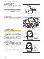
Valve Timing When Valve Clearance is 0 mm
Valve clearance 0 mm
5.15.2 Valve Timing When Valve Clearance is 2 mm
[0.08 in.]
Valve timing
Adjust the clearance to 2.5 mm [0.098 in.] for reliable
inspection, where the valve motion changes rapidly.
(1)
Insert a thickness gauge of 0.5 mm [0.020 in.] between
bridge cap and rocker arm.(Valve clearance 2 mm [0.08
in.])
(2)
Turn the crankshaft in the normal direction little by lit-
tle, and find a position where thickness gauge is tightly
gripped (valve open position) and a position where
thickness gauge is released (valve closed position.)
(3)
Check that the obtained angle meets the angle shown in
the illustration.
(4)
Readjust valve clearance to the correct value.
Valve Timing When Valve Clearance is 2 mm [0.08 in.]
Valve clearance 2 mm [0.08 in.]
55
q
55
q
65
q
65
q
Inlet valve
open
Top dead center
Bottom dead center
Inlet valve
closes
Exhaust valve
open
Exhaust valve
closes
Direction of
rotation
Rocker arm
Bridge cap
Thickness
gauge
Standard valve clearance
11
°
11
°
21
°
21
°
Top dead center
Bottom dead center
Inlet valve
open
Inlet valve
closes
Exhaust valve
closes
Exhaust valve
open
Direction of
rotation
Rocker arm
Bridge cap
Thickness
gauge
0.5 mm [0.020 in.]
Valve clearance 2 mm [0.08 in.]
Summary of Contents for S12A2
Page 1: ...SERVICE MANUAL September 2010 Pub No 99269 20170 199269 20170 ...
Page 2: ......
Page 16: ......
Page 20: ......
Page 42: ......
Page 44: ......
Page 68: ......
Page 69: ...3 1 Chapter 3 SERVICE TOOLS 1 Special Tools 3 3 ...
Page 70: ......
Page 78: ......
Page 82: ......
Page 136: ......
Page 174: ......
Page 218: ......
Page 220: ......
Page 242: ......
Page 244: ......
Page 294: ......
Page 310: ......
Page 320: ......
Page 322: ......
Page 334: ......
Page 354: ......

