


8. BUS CONNECTION
8.4 Precautions
8 - 41
8
BUS CONNECTION
8.4.14
When connecting to a
Q4ARCPU redundant system
(1) When the GOT is bus-connected to a Q4ARCPU
redundant system
Connect the GOT to the last redundant extension base
unit (A68RB) of the Q4ARCPU redundant system.
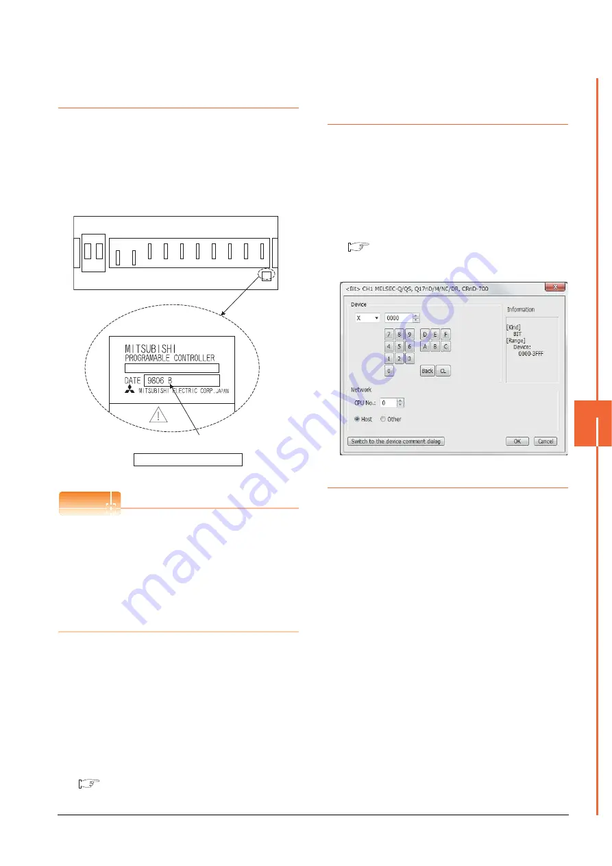
For the redundant extension base units, use version B
or later.
The version can be confirmed in the DATE field of the
rating plate.
POINT
POINT
POINT
Precautions for Q4ARCPU redundant system
configurations
The GOT does not operate normally in the following
system configurations.
(1) When the GOT is bus connected to the bus
switching module (A6RAF) on a redundant main
base unit (A32RB/A33RB)
(2) When the GOT is bus connected to a version-A
redundant main base unit (A68RB)
(2) Power-On sequence for GOT and Q4ARCPU
redundant system
Apply the power to the GOT and Q4ARCPU redundant
system in the following sequence.
1.
Turn ON the GOT.
2.
After the monitor screen is displayed on the GOT, turn
ON the Q4ARCPU redundant system.
At this time, a timeout is displayed on the system
alarm. Use System Information to reset the alarm.
For the system alarm, refer to the following manual:
GT Designer3 (GOT2000) Help
8.4.15
When monitoring the
Q170MCPU, Q170MSCPU(-
S1)
Set [CPU No.] to "2" in the device setting to monitor the
device of the Motion CPU area (CPU No.2).
When the CPU No. is set to "0" or "1", the device on the
PLC CPU area (CPU No.1) is monitored.
When the CPU No. is set to the number other than "0" to
"2", a communication error occurs and the monitoring
cannot be executed.
For setting the CPU No., refer to the following manual.
GT Designer3 (GOT2000) Help
Example) Setting dialog box of the bit device
8.4.16
Troubleshooting
For the troubleshooting, refer to the User's Manual for the
GOT you are using.
Caution
Version of redundant extension base unit
Enlarged view of rating plate
Summary of Contents for GOT2000 Series
Page 2: ......
Page 62: ...1 38 1 PREPARATORY PROCEDURES FOR MONITORING 1 6 Checking for Normal Monitoring ...
Page 64: ......
Page 80: ...2 16 2 DEVICE RANGE THAT CAN BE SET 2 6 MELSEC WS ...
Page 246: ...7 26 7 COMPUTER LINK CONNECTION 7 6 Precautions ...
Page 252: ...8 6 8 BUS CONNECTION 8 1 Connectable Model List ...
Page 256: ...8 10 8 BUS CONNECTION 8 2 System Configuration ...
Page 288: ...8 42 8 BUS CONNECTION 8 4 Precautions ...
Page 324: ...9 36 9 MELSECNET H CONNECTION PLC TO PLC NETWORK MELSECNET 10 CONNECTION PLC TO PLC NETWORK ...
Page 416: ......
Page 510: ...15 46 15 SERVO AMPLIFIER CONNECTION 15 7 Precautions ...
Page 518: ...16 8 16 ROBOT CONTROLLER CONNECTION 16 6 Precautions ...
Page 540: ...17 22 17 CNC CONNECTION 17 7 Precautions ...
Page 541: ...MULTIPLE GOT CONNECTIONS 18 GOT MULTI DROP CONNECTION 18 1 ...
Page 542: ......
Page 567: ...MULTI CHANNEL FUNCTION 19 MULTI CHANNEL FUNCTION 19 1 ...
Page 568: ......
Page 599: ...FA TRANSPARENT FUNCTION 20 FA TRANSPARENT FUNCTION 20 1 ...
Page 600: ......
Page 668: ...20 68 20 FA TRANSPARENT FUNCTION 20 7 Precautions ...
Page 670: ...REVISIONS 2 ...
Page 673: ......


