


5. ETHERNET CONNECTION
5.4 PLC Side Setting
5 - 41
5
ETHERN
ET C
O
NN
ECTION
5.4.8
Connecting to Built-in
Ethernet port FXCPU
(FX
3GE
)
This section describes the settings of the GOT and
Ethernet module (FX Series) in the following case of the
system configuration.
POINT
POINT
POINT
FX
3GE
For details of FX
3GE
, refer to the following manual.
FX
3GE
SERIES PROGRAMMABLE
CONTROLLERS HARDWARE MANUAL
System configuration
*1
These setting items do not exist at the PLC side. However,
the virtual values must be set on the GOT side.
■
[Controller Setting] and [Ethernet] of GT
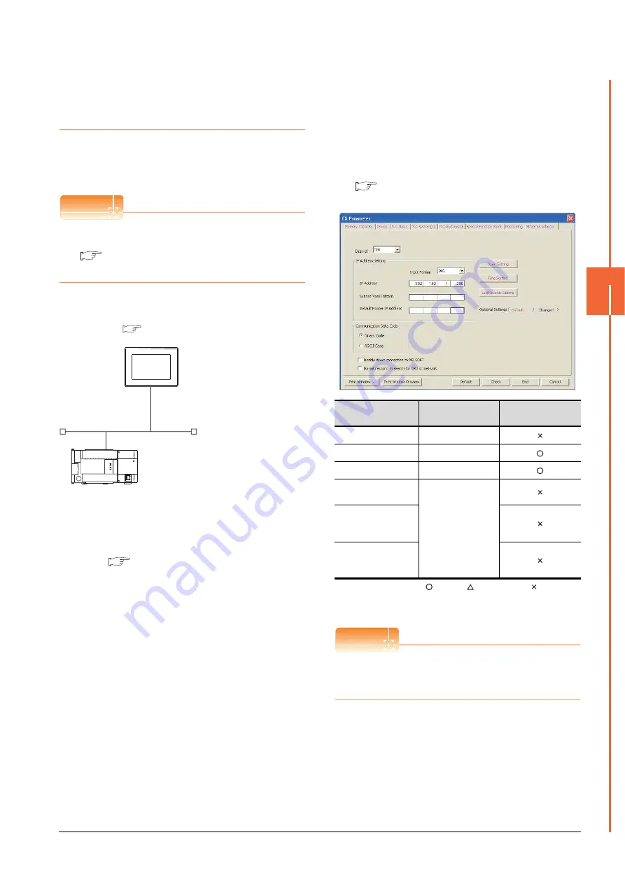
Ethernet parameter settings of FX
3GE
(1) Ethernet settings
Set the Ethernet parameter at [FX Parameter] on GX
Works2.
To set FX
3GE
, GX Works2 Ver.1.91V or later is required.
For details on the setting of FX
3GE
, refer to the following
manual.
FX
3GE
SERIES PROGRAMMABLE
CONTROLLERS HARDWARE MANUAL
:Required
:Set if necessary
:Not required
*1
The default value of IP address is 192.168.1.250. Set the IP
address corresponding to the system configuration.
POINT
POINT
POINT
When changing Ethernet parameter
After writing Ethernet parameters to the PLC CPU, turn
the PLC CPU OFF then back ON again.
<GOT>
(The settings other than the
following are set to the default)
PLC No.
: 1
IP address
: 192.168.0.18
Port No.
: 5019
Communication
format
: TCP (fixed)
PC No.
: 2 (virtual)
Network No.
: 1 (virtual)
IP address
: 192.168.0.19
Port No.
: 5556 (fixed)
Communication
format
: TCP (fixed)
<Ethernet module> (The settings other than the
following are set to the default)
*1
*1
[Controller Setting] and [Ethernet] of GT
Designer3
■
Item
Setting
Setting
(with GOT connected)
Channel
CH1
IP Address
192.168.1.250
*1
Open Settings
Refer to (2).
Communication Data
Code
(Use default value.)
Disable direct
connection to
MELSOFT
Do not respond to
search for CPU on
network
Summary of Contents for GOT2000 Series
Page 2: ......
Page 62: ...1 38 1 PREPARATORY PROCEDURES FOR MONITORING 1 6 Checking for Normal Monitoring ...
Page 64: ......
Page 80: ...2 16 2 DEVICE RANGE THAT CAN BE SET 2 6 MELSEC WS ...
Page 246: ...7 26 7 COMPUTER LINK CONNECTION 7 6 Precautions ...
Page 252: ...8 6 8 BUS CONNECTION 8 1 Connectable Model List ...
Page 256: ...8 10 8 BUS CONNECTION 8 2 System Configuration ...
Page 288: ...8 42 8 BUS CONNECTION 8 4 Precautions ...
Page 324: ...9 36 9 MELSECNET H CONNECTION PLC TO PLC NETWORK MELSECNET 10 CONNECTION PLC TO PLC NETWORK ...
Page 416: ......
Page 510: ...15 46 15 SERVO AMPLIFIER CONNECTION 15 7 Precautions ...
Page 518: ...16 8 16 ROBOT CONTROLLER CONNECTION 16 6 Precautions ...
Page 540: ...17 22 17 CNC CONNECTION 17 7 Precautions ...
Page 541: ...MULTIPLE GOT CONNECTIONS 18 GOT MULTI DROP CONNECTION 18 1 ...
Page 542: ......
Page 567: ...MULTI CHANNEL FUNCTION 19 MULTI CHANNEL FUNCTION 19 1 ...
Page 568: ......
Page 599: ...FA TRANSPARENT FUNCTION 20 FA TRANSPARENT FUNCTION 20 1 ...
Page 600: ......
Page 668: ...20 68 20 FA TRANSPARENT FUNCTION 20 7 Precautions ...
Page 670: ...REVISIONS 2 ...
Page 673: ......


