background image

23

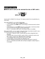
MODE switch setting

MODE switch works as the extended function of SIZE switch.

MODE

MULTI SINGLE EXP.

Set this switch to SINGLE for normal use. The image is printed in the size specified by the
SIZE switch.

When selecting MULTI, you can print 2-multi images.

To print a multi image, press the PRINT button twice.

At the first press of the PRINT button, the first image is memorized and the indicator
displays 

.

At the second press of the PRINT button, the second image is memorized and both
the first and the second images are printed automatically.

When 1:1 is selected by SIZE switch, multi image printing is not available.

When selecting EXP., you can enlarge or reduce the image to be printed in the NOR. size or
the SIDE size according to the setting of the SIZE switch.

When EXP. is selected, the EXP. indicator lights up and the enlargement ratio is
displayed.

The switch does not stay at the EXP. position. When you release the switch at the
EXP. position, it returns to the SINGLE position automatically.

The enlargement ratio can be set from 0.5 to 2.0 by 0.1 steps.

Use the ADJUST control to change the enlargement ratio.

The fixed enlargement ratio will not be lost even when the power is turned off.

When 1:1 is selected by the SIZE switch, printing of enlarged or reduced images is
not available.

Summary of Contents for P93E

Page 1: ...t industrial premises and on small scale enterprises inside as well as outside of the buildings All places of operation are characterised by their connection to the public low voltage power supply system VIDEOCOPYPROCESSOR MODEL P93W P93E OPERATION MANUAL THISOPERATIONMANUALISIMPORTANT TO YOU PLEASEREADITBEFOREUSINGYOUR VIDEOCOPYPROCESSOR VIDEOCOPY PROCESSOR OPEN PRINT COPY FEED FUNC CONT BRT ADJU...

Page 2: ...IEC320 2 2 E type 125V 10A or higher rating plug Case 4 Connect to the 230V receptacle of the host equipment The AC power cord should be UL or CSA approved and consist of type SJT size 16 or 18AWG length 2 5m or shorter cord with IEC320 C13 type 250V 10A or higher rating connector and IEC320 2 2 E type 250V 10A or higher rating plug NOTE This equipment has been tested and found to comply with the ...

Page 3: ...anual it may cause interference to other equipment and or other risk To prevent fire or shock hazard do not expose this appliance to rain or moisture This appliance must be earthed In Europe use the AC power cord according to the recommendations as below in order to comply with EN60601 1 and EN60950 Connect to the 230V receptacle of the room or the host equipment The AC power cord should be VDE ap...

Page 4: ... 8 8 8 8 8 ADJUSTMENT OF PRINT PICTURE Adjustment of Brightness Contrast 14 15 9 9 9 9 9 SETTING FUNCTION MODE Function mode 16 Setting the function mode 17 21 SIZE switch setting 22 MODE switch setting 23 Print patterns depending on the combination of the settings of the SIZE and MODE switches 24 User setting 25 Resetting the set values 25 A A A A A ERROR DISPLAY 26 28 B B B B B DIP SWITCH FUNCTI...

Page 5: ...ikely to be formed If dew is formed printing is not possible OPERATING AMBIENT TEMPERATURE RANGE The operating ambient temperature range is 5 C 40 C 41 F 104 F and humidity of 20 80 BE CAREFUL AROUND PRINT PAPER EXIT SLOT Do not insert your hand or any material into the paper exit slot during printing Do not touch the cutter blade inside the paper exit slot Otherwise your finger will be injured DO...

Page 6: ...CE Turn off the MAIN power switch and unplug the power cord during a long absence THERMAL PAPER 2 Thermal papers listed in the page of SPECIFICA TIONS are available 2 When the remaining length of the paper is about10 25cm a color belt appears at the paper end Prepare for replacement of the paper If the remaining paper length is less than 10 25cm printing becomes uneven due to the uneven paper core...

Page 7: ...h the instructions for use Any service after expiration of the warranty period will be chargeable Consult your dealer for advice TECHNICAL DESCRIPTION The supplier will make available on request such circuit diagrams component part lists descriptions calibration instructions or other information which will assist the USER s ap propriately qualified technical personnel to repair those parts of the ...

Page 8: ...nit out of the box carefully Take the unit out of the box by the following procedures Make sure to check the contents 4 4 4 4 4 Unwrap the unit BRT FUNC CONT COPY FEED PRINT ADJUST BRT CONT EXP SIZE SIZE 1 1 NOR MODE MULTI EXP SINGLE Accessories Cleaning paper Operation manual Thermal paper AC power cord BNC BNC connection cable Wired remote control ...

Page 9: ...1 23 D Displays stand by functions and error messages Indicator BRT CONT EXP Displays the function being set 7 BRT brightness button 6 4 7 8 Turn to change the settings of each function 16 Selects the function mode FUNC function button 9 A Press to feed the paper FEED button Lever Switch to open the door D SIZE switch 15 14 12 8 9 A B C Sets the contrast of the print image 8 CONT contrast button 1...

Page 10: ... to the installation instruction of equipment to be connected G H I J F K Name Function 10 11 29 DIP switch Selects special functions Video signal input VIDEO IN connector BNC type Video signal output Monitor output VIDEO OUT connector BNC type Remote control terminal Terminal to connect the remote control Power terminal AC LINE Potential equalization terminal Connect the power cord to this termin...

Page 11: ...ting side up When the paper roll is placed inversely images can not be printed OPEN Switch the lever located on the left side to the OPEN position The door opens printing side Place the paper roll in the printer 2 Load the paper roll 1 Open the door Pull out the first 15 20cm 6 in 9 in of the paper to remove any slack in the roll Paper High density paper KP65HM CE 3 Pull out the paper end 4 Close ...

Page 12: ...fed out skewed from the print exit adjust the paper position so that it is fed out straight Do not allow slack in the paper roll Set the paper tightly to remove any slack Ifthesideoftheprintpaperisunevenorthecoreisstickingout theamountofpaperfeeding after printing may vary When the side of paper is uneven or the core is sticking out install the print paper after making the paper side even The core...

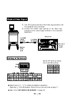
Page 13: ...d equipment Video signal equipment Television Video disc player Camera type VCR Monitor VCR Setting of Switches AC LINE REMOTE ON OFF VIDEO IN OUT DIP SW DIP SW FUNCTION TABLE NO 1 2 3 4 5 6 FUNCTION IMP TRAP MEMORY RESERVED SW ON 75Ω ON FIELD SW OFF HIGH OFF FRAME Rear panel To VIDEO OUT terminal To VIDEO input terminal Connect Power cord To VIDEO IN terminal To VIDEO output terminal SW NO Settin...

Page 14: ...ON IMP TRAP MEMORY RESERVED SW ON 75Ω ON FIELD SW OFF HIGH OFF FRAME Set the DIP switch as follows This is standard setting DIP SW FUNCTION TABLE NO 1 2 3 4 5 6 FUNCTION IMP TRAP MEMORY RESERVED SW ON 75Ω ON FIELD SW OFF HIGH OFF FRAME Setting of Switches 2 Select γ curve for ultrasonic diagnosis equipment Especially is recommended Refer to the γ curve set mode on page 17 2 Refer to the DIP SWITCH...

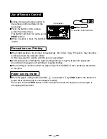
Page 15: ...ure as many times as you desire by pressing the COPY button When pressing the FEED button during copy printing the copy printing is canceled upon completion of the current copy 2 To feed the paper hold down the FEED button on the front panel 1 Turn on the power 3 Cut the printed paper 2 Print a picture displayed on the screen Paper Feeding Copy Printing Press the POWER switch to turn on the power ...

Page 16: ...oled down Avoid pulling out or holding the paper during printing or copying to prevent paper jam Do not touch the paper until printing or copying finishes When printing is carried out with no signal input NO SIGNAL will be printed at the bottom of the print Rear panel AC LINE REMOTE ON OFF VIDEO IN OUT DIP SW DIP SW FUNCTION TABLE NO 1 2 3 4 5 6 FUNCTION IMP TRAP MEMORY RESERVED SW ON 75Ω ON FIELD...

Page 17: ...stment use the BRT button BRT CONT button CONT and ADJUST control ADJUST 1 Press the buttons to adjust brightness or contrast OPEN PRINT COPY FEED FUNC CONT BRT ADJUST BRT CONT EXP SIZE MODE SIDE MULTI NOR 1 1 SINGLE EXP OPEN PRINT COPY FEED FUNC CONT BRT ADJUST BRT CONT EXP SIZE MODE SIDE MULTI NOR 1 1 SINGLE EXP Press the BRT button BRT to adjust the brightness The BRT indicator lights up Press ...

Page 18: ...memorized value will not be lost even when the power is turned off Turn the control clockwise to increase the value 3 Store the set value ADJUST ADJUST Turn the control counterclockwise to decrease the value The setting value is displayed by the indicator example Setting range is 19 to 19 ...

Page 19: ...opy printing 1 Setting of the horizontal print area for the enlarged image 2 Setting of the vertical print area for the enlarged image 2 Printing of the setting values SCAN setting IMAGE setting DIRECTION setting SAVING setting PAPER setting PRINT button function setting Setting of the number of prints Setting of the mode table printing 1 Displayed only when the MODE switch is set to MULTI 2 Displ...

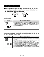
Page 20: ...image from the last 10 printed images to print it again The larger the number displayed by the indicator becomes the older the selected image is Selectable range 0 to 9 The selected image is displayed on the monitor The image selected in this mode is specified automatically as the first image the image printed on the right for 2 multi image copy printing The selected image is kept until a new imag...

Page 21: ...ize Because the print area is shown on the monitor you can adjust the print area viewing the monitor and shift the print area by turning the ADJUST control You can adjust the print area just vertically in this mode If you expand the print area horizontally the whole image is enlarged Indicator Selection of the second image for the multi image copy printing Purpose and description You can select an...

Page 22: ...Positive print Negative print When positive printing is selected the image is printed as displayed When negative printing is selected the image is printed inversed Indicator Printing of the setting values Purpose and description You can include the setting values of BRT CONT and GAMMA in the print at the bottom The setting values are not printed The setting values are printed A A A A Underscan Ove...

Page 23: ...any of the following options according to the paper to be used High glossy paper KP91HG CE High density paper KP65HM CE KP65H CE Standard paper KP61B CE KP61S CE Indicator DIRECTION setting Purpose and description You can select the print direction Printing starts from the bottom of the image The image is rotated 180 Printing starts from the top of the image A A Normal Reverse Narrow Normal Normal...

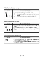
Page 24: ...umber of prints Purpose and description You can select the number of prints when you press the PRINT button The selectable number is to and continuous printing The continuous printing can be canceled by pressing the FEED button Indicator Setting of the mode table printing Purpose and description You can print the table of LED indications and the explanations corresponding to each function mode You...

Page 25: ...22 SIZE switch setting The size of the printed image can be selected by the SIZE switch SIZE SIDE NOR 1 1 Example A A A SIDE NOR 1 1 ...

Page 26: ... When 1 1 is selected by SIZE switch multi image printing is not available When selecting EXP you can enlarge or reduce the image to be printed in the NOR size or the SIDE size according to the setting of the SIZE switch When EXP is selected the EXP indicator lights up and the enlargement ratio is displayed The switch does not stay at the EXP position When you release the switch at the EXP positio...

Page 27: ...24 Print patterns depending on the combination of the settings of the SIZE and MODE switches B A A B A A A A Printing is not available Printing is not available SIZE MODE SIDE NOR 1 1 SINGLE MULTI EXP ...

Page 28: ...unit can memorize the settings which you adjusted to meet the operating conditions of the connected devices and the print quality conditions as the user setting When you change the setting by mistake you can correct it with a simple operation Memorizing the user setting 1 The service personnel of this unit memorizes the settings Contact your dealer Setting back to the user setting 1 Turn off the p...

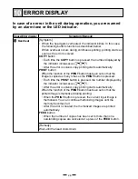
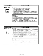
Page 29: ...utton When the function of the PRINT button has been set so that the image is copied as many times as the PRINT button is pressed Each time the PRINT button is pressed the number displayed by the indicator increases as After the error is solved copy printing starts automatically When the function of the PRINT button has been set so that the printed image is memorized during printing When the PRINT...

Page 30: ...le the printing of more than one copy has been suspended or there are images waiting to be processed an alarm tone is heard Then the paper is fed automati cally about 15 cm and printing resumes After the error is resolved the unit resumes printing from the inter rupted image and finishes printing all the outstanding images 3 3 3 3 3Button input error Symptom The button becomes invalid and an alarm...

Page 31: ... resolved the unit resumes printing from the interrupted image and finishes printing all the outstanding images Symptom When the thermal head does not automatically go down at the start of printing or paper feeding an alarm tone is heard When the thermal head does not automatically go up at the end of printing or paper feeding an alarm tone is heard The indicator displays and all the buttons becom...

Page 32: ...in normal use Set to ON when inputting a color signal ON The trap circuit is active OFF The trap circuit is inactive FRAME Set to FRAME position in normal use FIELD Set to FIELD position to print an image with rapid motion 2 The image displayed on the monitor is usually a single frame consisting of two fields Set to OFF These switches are not used ON OFF DIP SW DIP SW FUNCTION TABLE NO 1 2 3 4 5 6...

Page 33: ...y times as the PRINT button is pressed Image memorizing during printing Brightness adjustment Brightness index Copy status Image No in the memory Video output Through Normal stand by Through Through Freeze Freeze Image No in the memory Selection of the memorized image for multi copy printing Setting of the horizontal print area SCAN IMAGE DIRECTION SAVING Monitor Monitor PAPER Through Through Norm...

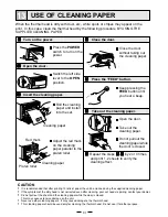
Page 34: ...r 7 7 7 7 7 Repeat the steps 3 3 3 3 3 6 6 6 6 6 by 2 or 3 times and print 1 2 sheets to verify the cleaning effect 4 4 4 4 4 Close the door 5 5 5 5 5 Press the FEED button 6 6 6 6 6 Take out the cleaning paper 1 1 1 1 1 Turn on the power CAUTION 0 It is recommended that after printing 10 rolls of paper the unit be cleaned using the supplied cleaning paper 0 If the symptom of the dirty head is not...

Page 35: ...e rubber roller is dirty with dust etc a blank spot may appear on the print In this case eliminate the dust on to the rubber roller with a blower or a brush Cleaning of Thermal Head When the thermal head is dirty with dust etc white spots or stripes may appear on the print In this case clean the thermal head according to 13 USE OF CLEANING PAPER Note After installation of new roll of paper dust on...

Page 36: ...1 104 F 5 40 C Humidity 20 80 RH No dewing External dimensions 6 1 x 3 5 x 10 1 154mm x 89 5mm x 256mm W x H x D Weight 6 2 lbs 2 8 kg Standard accessories BNC BNC connection cable 2m 1 piece AC power cord 1 piece Thermal paper KP65HM CE 1 roll Wired remote control 1 unit Cleaning paper 1 sheet Optional accessory Thermal paper KP65HM CE KP65H CE KP61S CE KP61B CE KP91HG CE SERVICE INFORMATION Befo...

Page 37: ...0835 Ratingen Germany Phone 2102 486 9250 FAX 2102 486 7320 French Branch 25 Boulevard des Bouvets 92741 NANTERRE cedex Phone 01 55 68 55 00 FAX 01 55 68 57 31 Italian Branch Centro Direzionale Colleoni Palazzo Perseo Ingresso 2 Via Paracelso 12 20041 Agrate Brianza Milano Italy Phone 039 60531 FAX 039 6057694 Benelux Branch Nijverheidsweg 23 A 3641 RP Postbus 222 3640 AE Mijdrecht Phone 02972 824...

Reviews: