54
4 STARTUP
4.2 Instructions on startup
4.2
Instructions on startup
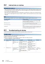
Instructions for power-on
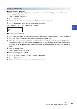
• When the absolute position detection system is used in a rotary servo motor, [AL. 025 Absolute position erased] occurs the
first time that the power is turned on and the servo motor cannot be changed to servo-on status. Shut off the power once,
then cycle the power to deactivate the alarm.
• If the power is turned on while the servo motor is being rotated by an external force, an alarm may occur. Make sure that
the servo motor is not operating before turning on the power. In addition, refer to the manual for the servo motor or encoder
being used.
Stop
If any of the following situations occur, the servo amplifier suspends and stops the operation of the servo motor.
4.3
Troubleshooting at startup
Problems that may occur at startup and the corresponding countermeasures are shown below.
Troubleshooting
If an alarm has occurred, refer to the following and remove the cause.
MR-J5 User's Manual (Troubleshooting)
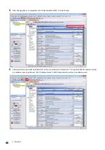
Additionally, investigate the cause by using MR Configurator2. Refer to the following for details.
Page 56 Investigation by using MR Configurator2.
Operation/command
Stopping condition
Alarm occurrence
The servo motor decelerates to a stop. There are also alarms that activate
and stop the dynamic brake. Refer to the following for the details of alarms.
MR-J5 User's Manual (Troubleshooting)
EM2 (Forced stop 2) off
The servo motor decelerates to a stop. [AL. 0E6 Servo forced stop warning]
occurs. In the torque mode, EM2 functions the same as EM1.
STO (STO1 and STO2) off
The base circuit is shut off and the dynamic brake operates to stop the servo
motor.
Limit switch off
When LSP (Forward rotation stroke end) or LSN (Reverse rotation stroke end)
is turned off, the servo motor comes to a quick stop and activates the servo-
lock. Operation in the opposite direction is possible.
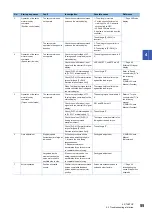
No.
Startup sequence
Fault
Investigation
Possible cause
Reference
1
Power-on
5-digit, 7-segment LED
is not lit.
5-digit, 7-segment LED
blinks.
The problem is not solved even if
the CN2 and CN3 connectors are
disconnected.
1. Power supply voltage failure.
2. The servo amplifier is
malfunctioning.
The problem is solved when the
CN2 connector is disconnected.
1. The power supply of encoder
cabling is shorted.
2. The encoder is malfunctioning.
The problem is solved when the
CN3 connector is disconnected.
The power supply of the CN3
cabling is shorted.
2
SON (Servo-on) on
The servo motor shaft is
not servo-locked.
(The servo motor shaft is
free.)
1. Check the display to see if the
servo amplifier is ready to
operate.
2. Check the external I/O signal
display to see if SON (Servo-on)
is on.
1. SON (Servo-on) is not switched
on. (The wiring is incorrect.)
2. 24 V DC power is not supplied
to DICOM.

